
User's Manual
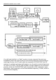
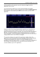
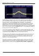
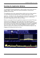
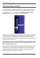
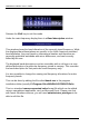
Table Of Contents
- Table of Contents
- Introduction
- The Hardware
- Installation
- Getting Started
- Inside the Excelsior
- Resizing the Application Window
- Drop-Down Menu Controls
- Tuning the Excelsior
- Receiver Selection
- Mode Selection
- Function Tabs
- Spectrum Scopes
- Recording Functions
- Attenuator
- Preamplifier
- S-meter
- Top Menu Bar
- File
- Options
- Auto-mute RX not in focus
- Enable second RX
- Filter Length
- Front Panel LED
- Display Offset
- Time
- Keyboard Shortcuts
- VSC Set-up
- Audio Buffering
- AMS Capture Range
- Audio Output
- Show Measurements
- Show Data Rates
- Of particular interest to many users will be the CPU load (excessive CPU load may cause sluggish behaviour or freezing of the computer), and Audio latency. Apart from DDC bandwidth, CPU load may be minimized by reducing the Demodulator filter length (...
- Note: When measuring sensitivity using SINAD, it is very important that the Audio Filter is enabled and the cut-off frequencies (and for FM measurements, also the de-emphasis) are set according to the specified test conditions. Proper audio filtering ...
- Show Waterfall Timestamps
- Calibration
- Hand-Off Receiver
- Color scheme
- Restore factory defaults
- Memory
- Scheduler
- Scanner
- Logger
- Plugins
- Power Switch
- Date and Time Display
- Appendix A – SDR and DDC Primer
- Appendix B – Troubleshooting
- Appendix C – USB Interface Diagnostics
- Appendix D – Dealing with Interference
- Appendix E – G39DDCi PCIe Card Connections
- Appendix F – Waterfall Spectrum Palettes
- Appendix G – Recording File Formats
- Appendix H – Compliance Declarations
- Appendix I – Safety Disposal

WiNRADiO G39DDC User’s Guide
24
In the particular class of software-defined receivers that the WiNRADiO
Excelsior represents, much of the hardware processing is replaced by
software. A large chunk of the received spectrum is digitized as a whole, and
out of this digitized spectrum data, a smaller chunk is selected by a process
called decimation and down-converted digitally, using a hardware component
called a Field-Programmable Gate Array (FPGA). The particular type of
FPGA used in the Excelsior contains 24,624 logic elements, 66 memory
blocks, 608,256 bits of RAM, 66 multipliers, 4 phase-lock loops and 215
programmable inputs or outputs.
The DDC is in fact a functional equivalent of the mixer, local oscillator and filter
- but rather than outputting an analog intermediate frequency signal, its output
is in a digital form. This digitally down-converted signal then arrives in the
computer via the USB or PCIe interface where it is filtered and demodulated
entirely in software, using purely computational digital signal processing
methods – there are no coils or crystals in the filters, and no diodes or
capacitors in the demodulator.
In the WiNRADiO Excelsior receiver, there are two separate DDC paths
corresponding to two independent, simultaneously operating receiver
channels. Each path consists of a primary DDC (DDC1) and secondary DDC
(DDC2).
You can control these two receiver channels using the two tabs (RX1 and
RX2) above the main frequency display. There are some important tuning
ramifications resulting from the fact that both of these two channels must
reside within the current 16 MHz wide IF spectrum (also commonly referred to
as “instantaneous” or “stare” spectrum) - this will be discussed in a greater
detail in a later chapter, Tuning the Excelsior.
For both RX channels, the primary DDC can digitize a large chunk of spectrum
anywhere within the 16 MHz IF spectrum. This chunk of spectrum can be
recorded and played back by the PC, making it possible to “re-receive” signals
located anywhere within that chunk. The maximum width of the DDC1 chunk
(DDC1 bandwidth) is 4 MHz for both receiver channels, except in the WR-
G39DDCe models, where it remains 4 MHz for the first receiver channel but is
limited to 2 MHz for the second receiver channel. This limitation exists due to
throughput constraints of the USB interface.
The larger the DDC bandwidth, the more CPU processing power is required by
the computer. On slower computers, using the maximum DDC bandwidth may