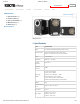
2/22/2018 ROBOTIS e-Manual Custom Search DYNAMIXEL PLATFORM STEAM SOFTWARE PARTS FAQ XM430-W210 Edit on GitHub 1. Specifications [+] 2. Control Table [+] 3. How to Assemble [+] 4. Maintenance [+] 5. Reference [+] Back to Top ▲ XM430-W210 1. Specifications http://emanual.robotis.com/docs/en/dxl/x/xm430-w210/ Item Specifications MCU ST CORTEX-M3 (STM32F103C8 @ 72Mhz, 32Bit) Position Sensor Contactless absolute encoder (12Bit, 360°) Maker : ams(www.ams.
/22/2018 XM430-W210 Back to Top ▲ ROBOTIS e-Manual Item Specifications No Load Speed 70rpm @ 11.1V 77rpm @ 12.0V 95rpm @ 14.8V Operating Temperature -5°C ~ +80°C Input Voltage 10.0 ~ 14.8V (Recommended : 12.
2/22/2018 ROBOTIS e-Manual Caution When connecting to power supply, it is recommended using ROBOTIS controller or SMPS2DYNAMIXEL. Do not connect or disconnect DYNAMIXEL when power is being supplied. XM430-W210 2. Control Table The Control Table is a structure of data implemented in the DYNAMIXEL. Users can read a specific Data to get status of the DYNAMIXEL with Read Instruction Packets, and modify Data as well to control DYNAMIXEL with WRITE Instruction Packets. Back to Top ▲ 2. 1.
2/22/2018 ROBOTIS e-Manual stands for read only access permission. Data with the read only property cannot be changed by the WRITE Instruction. Read only property(‘R’) is generally used for measuring and XM430-W210 monitoring purpose, and read write property(‘RW’) is used for controlling DYNAMIXEL. 2. 1. 4. Initial Value Back to Top ▲ Each data in the Control Table is restored to initial values when the DYNAMIXEL is turned on.
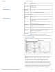
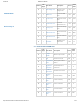
2/22/2018 XM430-W210 Back to Top ▲ ROBOTIS e-Manual Address Size (Byte) Access Initial Value 34 Minimum Input Voltage Limit RW 95 PWM Limit Maximum PWM Limit RW 885 2 Current Limit Maximum Current Limit RW 1193 40 4 Acceleration Limit Maximum Accleration Limit RW 32767 44 4 Velocity Limit Maximum Velocity Limit RW 480 48 4 Max Position Limit Maximum Position Limit RW 4095 52 4 Min Position Limit Minimum Position Limit RW 0 63 1 Shutdown Shutdown Error Informat
2/22/2018 XM430-W210 Back to Top ▲ http://emanual.robotis.
2/22/2018 XM430-W210 Back to Top ▲ http://emanual.robotis.
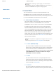
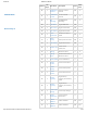
2/22/2018 XM430-W210 Back to Top ▲ ROBOTIS e-Manual Address Size (Byte) Data Name Description Access Initial Value 636 1 Indirect Data 31 Indirect Data 31 RW 0 … … … … … … 659 1 Indirect Data 54 Indirect Data 54 RW 0 660 1 Indirect Data 55 Indirect Data 55 RW 0 661 1 Indirect Data 56 Indirect Data 56 RW 0 Protocol 1.0 does not support addresses greater than 256. Therefore, Indirect Address 29 ~ 56 and Indirect Data 29 ~ 56 can only be accessed with Protocol 2.0.
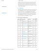
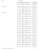
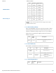
2/22/2018 ROBOTIS e-Manual Value Baud Rate Margin of Error 7 4.5M 0.000% 6 4M 0.000% 5 3M 0.000% 4 2M 0.000% 3 1M 0.000% 2 115,200 0.000% 1(Default) 57,600 0.000% 0 9,600 0.000% XM430-W210 Back to Top ▲ Less than 3% of the baud rate error margin will not affect to UART communication. Note 2. 4. 5. Return Delay Time(9) After the DYNAMIXEL receives an Instruction Packet, it delays transmitting the Status Packet for Return Delay Time (9).
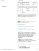
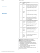
2/22/2018 ROBOTIS e-Manual Operating Mode Description 0 Current Control Mode DYNAMIXEL only controls current(torque) regardless of speed and position. This mode is ideal for a gripper or a system that only uses current(torque) control or a system that has additional velocity/position controllers. 1 Velocity Control Mode This mode controls velocity. This mode is identical to the Wheel Mode(endless) from existing DYNAMIXELs. This mode is ideal for wheel-type robots.
2/22/2018 XM430-W210 ROBOTIS e-Manual Note PWM is the abbreviation for Pulse Width Modulation that modulates PWM Duty to control motors. The PWM Control Mode changes pulse width to control average supply voltage to the motor and this technique is widely used in the motor control field. Therefore, PWM Control Mode uses Goal PWM(100) value to control supply voltage for DYNAMIXEL. PWM Control Mode is similar to the Wheel Mode of DYNAMIXEL AX and RX series. 2. 4. 8.
2/22/2018 ROBOTIS e-Manual 2. 4. 9. Protocol Version(13) Users can select Dynamixel protocol version (1.0 and 2.0). It is recommended to use an identical protocol version for multiple Dynamixels. XM430-W210 Value Protocol Version Compatible Dynamixels 1 1.0 AX Series, DX Series, RX Series, EX Series, MX Series with Firmware below v39 2(default) 2.0 MX-28/64/106 with Firmware v39 or above, X Series, Pro Series Back to Top ▲ The protocol 2.0 is greatly enhanced from the protocol 1.0.
2/22/2018 ROBOTIS e-Manual This value limits operating temperature. When the Present Temperature(146) that indicates internal temperature of Dynamixel is greater than the Temperature Limit(31), the Over Heating Error Bit(0x04) and Hardware Error XM430-W210 Bit(0x80) in the Hardware Error Status(70) will be set. If Overheating Error Bit(0x04) is configured in the Shutdown(63), Torque Enable(64) is cleared to ‘0’ and Torque will be disabled. For more details, please refer to the Shutdown(63) section.
2/22/2018 ROBOTIS e-Manual This value indicates maximum current(torque) output limit. Goal Current(102) can’t be configured with any values XM430-W210 Back to Top ▲ exceeding Current Limit(38). The Current Limit(38) is used in Torque Control Mode and Current-based Position Control Mode, therefore decreasing Current Limit(38) will result in decreasing torque of DYNAMIXEL. For more details, please refer to the Position PID Gain(80 ~ 84). Unit Value Range about 2.
2/22/2018 XM430-W210 ROBOTIS e-Manual Unit Value Range 0.088° 0 ~ 4,095(1 rotation) Note Max Position Limit(48) and Min Position Limit(52) are only used in Position Control Mode with a single turn. 2. 4. 19. Shutdown(63) The Dynamixel can protect itself by detecting dangerous Back to Top ▲ situations that could occur during the operation. Each Bit is inclusively processed with the ‘OR’ logic, therefore, multiple options can be generated.
2/22/2018 ROBOTIS e-Manual Manual.) If Shutdown occurs, LED will flicker every second.(Firmware v41 or above) XM430-W210 2. 4. 20. Torque Enable(64) Controls Torque ON/OFF. Writing ‘1’ to this address will turn on the Torque and all Data in the EEPROM area will be protected.
2/22/2018 ROBOTIS e-Manual 2. 4. 23. Registered Instruction(69) Value XM430-W210 Description 0 REG_WRITE instruction is not received 1 REG_WRITE instruction is received Note If ACTION instruction is executed, the value will be changed to 0. 2. 4. 24. Hardware Error Status(70) Back to Top ▲ This value indicates hardware error status. The Dynamixel can protect itself by detecting dangerous situations that could occur during the operation.
2/22/2018 ROBOTIS e-Manual If Shutdown occurs, use below method to reboot Dynamixels. Note XM430-W210 1. H/W REBOOT : Turn off the power and turn on again 2. S/W REBOOT : Transmit REBOOT Instruction (For more details, please refer to the [Reboot] section of Protocol eManual.) If Shutdown occurs, LED will flicker every second.(Firmware v41 or above) Back to Top ▲ 2. 4. 25. Velocity PI Gain(76, 78) These values indicate Gains of Velocity Control Mode.
2/22/2018 ROBOTIS e-Manual XM430-W210 Note Back to Top ▲ Ka stands for Anti-windup Gain and ‘β’ is a conversion coefficient of position and velocity that cannot be modified by users. For more details about the PID controller, please refer to the PID Controller at wikipedia. 2. 4. 26. Position PID Gain(80, 82, 84), Feedforward 1st/2nd Gains(88, 90) These Gains are used in Position Control Mode and Extended Position Control Mode.
2/22/2018 ROBOTIS e-Manual 2. Goal Position(116) is converted to target position trajectory XM430-W210 Back to Top ▲ and target velocity trajectory by Profile Velocity(112) and Profile Acceleration(108). 3. The target position trajectory and target velocity trajectory is stored at Position Trajectory(140) and Velocity Trajectory(136) respectively. 4. Feedforward and PID controller calculate PWM output for the motor based on target trajectories. 5.
2/22/2018 ROBOTIS e-Manual 4. Goal PWM(100) sets a limit on the calculated PWM output and decides the final PWM value. XM430-W210 5. The final PWM value is applied to the motor through an Inverter, and the horn of DYNAMIXEL is driven. 6. Results are stored at Present Position(132), Present Velocity(128), Present PWM(124) and Present Current(126). Back to Top ▲ Note Ka is an Anti-windup Gain that cannot be modified by users.
2/22/2018 ROBOTIS e-Manual packet. If the value of Bus Watchdog (98) is changed to ‘0’, Bus Watchdog Error will be cleared. For details of Range Error, please refer to the protocol of the e-Manual. Note XM430-W210 The following are examples of the operation of the Bus Watchdog function. 1. After setting the operating mode (11) to speed control Back to Top ▲ mode, change the Torque Enable (64) to ‘1’. 2. If ‘50’ is written in the Goal Velocity (104), the DYNAMIXEL will rotate in CCW direction. 3.
2/22/2018 XM430-W210 ROBOTIS e-Manual Unit Value Range about 2.69[mA] -Current Limit(38) ~ Current Limit(38) Note Applying high current to the motor for long period of time might damage the motor. 2. 4. 30. Goal Velocity(104) In case of Velocity Control Mode, Goal Velocity(104) can be Back to Top ▲ used to set a target velocity. This value cannot exceed Velocity Limit(44). For now, Goal Velocity(104) is used for target velocity, but this value is not used to limit the velocity.
2/22/2018 XM430-W210 Back to Top ▲ ROBOTIS e-Manual Unit Value Range Description 0.229 rpm 0 ~ Velocity Limit(44) ‘0’ stands for an infinite velocity The Profile is an acceleration/deceleration control method to reduce vibration, noise and load of the motor by controlling dramatically changing velocity and acceleration. It is also called Velocity Profile as it controls acceleration and deceleration based on velocity. DYNAMIXEL provides 4 different types of Profile.
2/22/2018 ROBOTIS e-Manual distance difference between target position and current position). XM430-W210 4. Selected Profile type is stored at Moving Status(123).(Refer to the Moving Status(123)) 5. Dynamixel is driven by the calculated target trajectory from Profile. 6. Target velocity trajectory and target position trajectory from Profile are stored at Velocity Trajectory(136) and Position Trajectory(140) respectively. 7.
2/22/2018 ROBOTIS e-Manual be calculated as below equation. t1 = 64 * {Goal Velocity(104) / Profile Acceleration(108)} 2. 4. 33. Goal Position(116) XM430-W210 Target position can be set with Goal Position(116). From the front view of Dynamixels, CCW is an increasing direction whereas CW is a decreasing direction. The way to reaching Goal Position(116) is differ by 4 Profiles provided by Dynamixels. Please refer to the Profile Velocity(112) for more details.
2/22/2018 ROBOTIS e-Manual This value indicates whether Dynamixel is in motion or not. If absolute value of Present Velocity(128) is greater than Moving Threshold(24), Moving(122) is set to ‘1’. Otherwise, it will be XM430-W210 cleared to ‘0’. However, this value will always be set to ‘1’ regardless of Present Velocity(128) while Profile is in progress with Goal Position(116) instruction.
2/22/2018 ROBOTIS e-Manual This value indicates current Current. For more details, please refer to the Goal Current(102). 2. 4. 39. Present Velocity(128) XM430-W210 This value indicates current Velocity. For more details, please refer to the Goal Velocity(104)](#goal-velocity). 2. 4. 40. Present Position(132) This value indicates present Position. For more details, please refer to the Goal Position(116).
2/22/2018 ROBOTIS e-Manual This value indicates present voltage that is being supplied. For more details, please refer to the Max/Min Voltage Limit(32, 34). XM430-W210 2. 4. 44. Present Temperature(146) This value indicates internal temperature of Dynamixel. For more details, please refer to the Temperature Limit(31). 2. 4. 45. Indirect Address, Indirect Data Back to Top ▲ Indirect Address and Indirect Data are useful when accessing two remote addresses in the Control Table as sequential addresses.
2/22/2018 XM430-W210 Back to Top ▲ ROBOTIS e-Manual Indirect Address Range Description 64 ~ 661 EEPROM address can’t be assigned to Indirect Address In order to allocate Data in the Control Table longer than 2[byte] to Indirect Address, all address must be allocated to Indirect Address like the above Example 2. Note Note Indirect Address 29 ~ 56 and Indirect Data 29 ~ 56 can only be accessed with Protocol 2.0. 3. How to Assemble 3. 1. Wiring through Back Case http://emanual.robotis.
2/22/2018 ROBOTIS e-Manual Caution XM430-W210 Dynamixel X-Series cable assembly through hollow case Organize the entangled cable before assembling the back case. Do not assemble the back case with entangled cable. The entangled cable can be squashed by the case and cause communication error. 3. 2. Option Frame Assembly Back to Top ▲ 4. Maintenance 4. 1. Horn and Bearing Replacement http://emanual.robotis.
2/22/2018 ROBOTIS e-Manual The horn is installed on the front wheel gear serration of the DYNAMIXEL whereas the bearing set is installed on the back. XM430-W210 Back to Top ▲ 4. 1. 1. Installing the Horn Place the thrust horn washer into the actuator before inserting the horn. You must carefully align the horn to the wheel gear serration by aligning dots. Once alignment is properly done, gently push the center of the horn toward the actuator.
2/22/2018 ROBOTIS e-Manual XM430-W210 5. Reference Back to Top ▲ Note Compatibility Guide 5. 1. Quick Start 5. 1. 0. 1. Prerequisites Power supply to DYNAMIXEL(12V SMPS / Controllers) PC with Windows or OSX Connection between PC and DYNAMIXEL (Micro USB cable) 5. 1. 0. 2. R+ Manager 2.0 Install In order to change settings of DYNAMIXEL, R+ Manager 2.0 must be installed on your system. You can also use Dynamixel SDK or Dynamixel Workbench. 5. 2.
2/22/2018 ROBOTIS e-Manual Download X_430_std_ref.pdf © 2018 ROBOTIS. Powered by Jekyll & Minimal Mistakes. XM430-W210 Back to Top ▲ http://emanual.robotis.