
Data Sheet
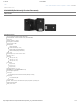

1/11/2018 XL430-W250
http://support.robotis.com/en/product/actuator/dynamixel_x/xl_series/xl430-w250.htm 8/15
Note : K
a
stands for Anti-windup Gain and ‘β’ is a conversion coefficient of position and velocity that cannot be modified by users. For more details about the PID controller, please refer to the below
website.
http://en.wikipedia.org/wiki/PID_controller
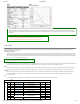
Position D Gain (80), Position I Gain (82), Position P Gain (84)
Feedforward 2nd Gain (88), Feedforward 1st Gain (90)
These Gains are used in Position Control Mode and Extended Position Control Mode. Gains of Dynamixel’s internal controller can be calculated from Gains of the Control Table as shown below. The
constant in each equations include sampling time. Position P Gain of Dynamixel’s internal controller is abbreviated to K
P
P and that of the Control Table is abbreviated to K
P
P
(TBL)
.
Controller Gain Conversion Equation Range Description
Position D Gain(80)
K
P
D K
P
D = K
P
D
(TBL)
/ 16
0 ~ 16383 D Gain
Position I Gain(82)
K
P
I K
P
I = K
P
I
(TBL)
/ 65536
0 ~ 16383 I Gain
Position P Gain(84)
K
P
P K
P
P = K
P
P
(TBL)
/ 128
0 ~ 16383
P Gain
Feedforward 2nd Gain(88)
K
FF2nd
K
FF2nd
= K
FF2nd(TBL)
/ 4
0 ~ 16383
Feedforward Acceleration Gain
Feedforward 1st Gain(90)
K
FF1st
KFF1st = K
FF1st(TBL)
/ 4
0 ~ 16383
Feedforward Velocity Gain
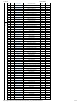
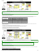
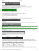
Below figure is a block diagram describing the position controller in Position Control Mode and Extended Position Control Mode. When the instruction from the user is received by Dynamixel, it takes
following steps until driving the horn.
① An Instruction from the user is transmitted via Dynamixel bus, then registered to Goal Position(116).
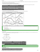
② Goal Position(116) is converted to target position trajectory and target velocity trajectory by Profile Velocity(112) and Profile Acceleration(108).
③ The target position trajectory and target velocity trajectory is stored at Position Trajectory(140) and Velocity Trajectory(136) respectively.
④ Feedforward and PID controller calculate PWM output for the motor based on target trajectories.
⑤ Goal PWM(100) sets a limit on the calculated PWM output and decides the final PWM value.
⑥ The final PWM value is applied to the motor through an Inverter, and the horn of Dynamixel is driven.
⑦ Results are stored at Present Position(132), Present Velocity(128), Present PWM(124) and Present Load(126).
Note1) : In case of PWM Control Mode, both PID controller and Feedforward controller are deactivated while Goal PWM(100) value is directly controlling the motor through an Inverter. In this manner,
users can directly control the supplying voltage to the motor.
Note2) : K
a
is an Anti-windup Gain that cannot be modified by users. For more details about the PID controller and Feedforward controller, please refer to the below websites.
http://en.wikipedia.org/wiki/PID_controller
https://en.wikipedia.org/wiki/Feed_forward_(control)
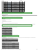
Bus Watchdog (98, Available after Firmware version 38)
Bus Watchdog (98) is a safety device (Fail-safe) that stops the Dynamixel if the communication between the controller and Dynamixel communication (RS485, TTL) is disconnected due to an unspecified
error.
Communication is defined as all the Instruction Packet in the Dynamixel Protocol.
Values Description