
Data Sheet

2/23/2018 XH-430-V350
http://support.robotis.com/en/product/actuator/dynamixel_x/xh_series/xh-430-v350.htm 4/15
Note : Protocol 1.0 does not support addresses greater than 256. Therefore, Indirect Address 29 ~ 56 and Indirect Data 29 ~ 56 can only be accessed with Protocol 2.0.
Address Description
EEPROM Area
Note : Any Data in EEPROM Area can only be modified when the value of Torque Enable(64) is cleared to ‘0’.
Model Number (0)
This address stores model number of the Dynamixel.
Firmware Version (6)
This address stores firmware version of the Dynamixel.
ID (7)
The ID is a unique value in the network to identify each Dynamixel with an Instruction Packet.
0~252 (0xFC) values can be used as an ID, and 254(0xFE) is occupied as a broadcast ID. The Broadcast ID(254, 0xFE) can send an Instruction Packet to all connected Dynamixels simultaneously.
Note : Please avoid using an identical ID for multiple Dynamixels. In order to change the ID in the EEPROM Area, Torque Enable(64) has to be cleared to ‘0’ in advance.
Note : Please avoid using an identical ID for multiple Dynamixels. In order to change the ID in the EEPROM Area, Torque Enable(64) has to be cleared to ‘0’ in advance.
Baud Rate (8)
Baud Rate determines serial communication speed between a controller and Dynamixels.
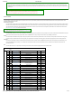
Baud Rate Baud Rate[bps] Margin of Error
0 9,600 0.000%
1(Default) 57,600 0.000%
2 115,200 0.000%
3 1M 0.000%
4 2M 0.000%
5 3M 0.000%
6 4M 0.000%
7 4.5M 0.000%
Note : Less than 3% of the baud rate error margin will not affect to UART communication.
Return Delay Time (9)
After the Dynamixel receives an Instruction Packet, it delays transmitting the Status Packet for Return Delay Time (9). For instance, if the Return Delay Time(9) is set to ‘10’, the Status Packet will be
returned after 20[μsec] when the Instruction Packet is received.
Values Description
Unit 2[μsec] -
Range 0 ~ 254 Default value ‘250’(500[μsec]), Maximum 508[μsec]
Drive Mode (10, Available after Firmware version 38)
Drive Mode Definition Values
Bit 7 0x80 - Unused, always ‘0’
Bit 6 0x40 - Unused, always ‘0’
Bit 5 0x20 - Unused, always ‘0’
Bit 4 0x10 - Unused, always ‘0’
Bit 3 0x08 - Unused, always ‘0’
Bit 2 0x04 - Unused, always ‘0’
Bit 1 0x02 - Unused, always ‘0’
Bit 0 0x01 Direction of rotation
Normal mode(‘0’) : CCW(Positive), CW(Negative)
Reverse mode(’1’) : CCW(Negative), CW(Positive)
Operating Mode (11)
Operating
Mode
Operating Mode Description
0 Current Control Mode
Dynamixel only controls current(torque) regardless of speed and position.
This mode is ideal for a gripper or a system that only uses current(torque) control or a system that has additional velocity/position controllers.
1
Velocity Control Mode
(0° ~ 360°)
This mode controls velocity.
This mode is identical to the Wheel Mode(endless) from existing Dynamixels. This mode is ideal for wheel-type robots.
3(Default) Position Control Mode This mode controls position.