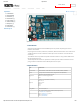
4/27/2018 OpenCR1.0 Custom Search DYNAMIXEL PLATFORM STEAM SOFTWARE PARTS FAQ OpenCR1.0 1. Introduction Edit on GitHub 2. Specifications 3. Hardware [+] 4. Bootloader [+] 5. Downloader [+] 6. Arduino IDE [+] 7. Examples [+] 8. Downloads 9. References [+] Back to Top ▲ OpenCR 1.0 1. Introduction OpenCR1.0 is developed for ROS embedded systems to provide completely open-source hardware and software.
4/27/2018 OpenCR1.0 Items Specifications LEDs and buttons LD2 (red/green) : USB communication User LED x 4 : LD3 (red), LD4 (green), LD5 (blue) User button x 2 External input source 5 V (USB VBUS), 7-24 V (Battery or SMPS) Default battery : LI-PO 11.1V 1,800mAh 19.98Wh Default SMPS: 12V 5A External output source * 12V max 5A(SMW250-02), * 5V max 4A(5267-02A), 3.3V@800mA(20010WS-02) OpenCR1.0 Powers External battery Port for RTC (Real Time Clock) (Molex 53047-0210) Power LED: LD1 (red, 3.
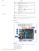
4/27/2018 OpenCR1.0 Item Description Compiler gcc arm 5.4 2016q2 OpenCR1.0 Back to Top ▲ USB Port Connected to PC and recognized as serial port A communication cable for downloading firmware through the bootloader. PUSH SW2 Press and hold the button when the power is on or reset to execute the bootloader If the button is not pressed when the power is turned on, the bootloader is executed. If the firmware is in the flash memory, the bootloader executes the firmware. 4. 1.
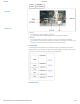
/27/2018 OpenCR1.0 OpenCR1.0 Back to Top ▲ If the board is powered on or reset, if the SW2 button is pressed, it waits for commands from the PC in the boot loader state. If the SW2 button is not pressed, jump to the firmware if the firmware exists in the firmware area of the flash memory and execute it. 4. 3. Communication Protocol 4. 3. 1. MavLink The communication protocol for downloading firmware from the boot loader uses MavLink.
4/27/2018 OpenCR1.0 The defined xml file should be converted to the command code of the language you want to use through the MavLink utility. Download the MavLink utility source code from github below. https://github.com/mavlink/mavlink/ OpenCR1.0 It is written in Python and requires Python 2.7 or later. If it is not installed, add it. $ sudo apt-get install python-tk $ sudo apt-get install python-future $ python mavgenerate.
4/27/2018 OpenCR1.0 OpenCR1.0 Back to Top ▲ 4. 3. 4. Message Processing In the code actually implemented, the main function calls the msg_process_vcp() function for message processing. In this case, if there is data coming from USB, msg_recv function is called to parse the message, and if any command is received, it returns TRUE to call the corresponding command function. http://emanual.robotis.
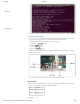
4/27/2018 OpenCR1.0 OpenCR1.0 int main(void) { tTime = millis(); while(1) { msg_process_vcp(); } } void msg_process_vcp(void) { BOOL ret; uint8_t ch; msg_t msg; while(vcp_is_available()) { ch = vcp_getch(); ret = msg_recv( 0, ch, &msg ); Back to Top ▲ if( ret == TRUE ) { switch( msg.p_msg->msgid ) { case MAVLINK_MSG_ID_READ_VERSION: cmd_read_version(&msg); break; case MAVLINK_MSG_ID_READ_BOARD_NAME: cmd_read_board_name(&msg); break; ... omit ...
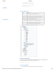
4/27/2018 OpenCR1.0 mav_ack.data[4] = boot_revision; mav_ack.data[5] = boot_revision>>8; mav_ack.data[6] = boot_revision>>16; mav_ack.data[7] = boot_revision>>24; mav_ack.length = 8; resp_ack(p_msg->ch, &mav_ack); OpenCR1.0 } } 4. 3. 5. Folder Structure Back to Top ▲ Item Contents bin Save obj and bin files generated after build common->bsp Includes board-specific functions (LED / BUTTON / USB, etc.
4/27/2018 OpenCR1.0 1. Hold down the Boot button. 2. Press the Reset button. 3. Release the Reset button. 4. Release the Boot button. OpenCR1.0 OpenCR will enter the DFU mode after reset by the built-in boot loader. Back to Top ▲ 4. 4. 2. Check Boot Mode If you run lsusb, you can check if it is in DFU mode. If the MCU is in DFU mode, the DFU device will be displayed after running lsusb. $ lsusb 4. 4. 3.
4/27/2018 OpenCR1.0 OpenCR1.0 Back to Top ▲ 4. 5. Firmware Recovery Mode If currupted or incompleted firmware is downloaded and the board freezes or does not work, you must enter the boot loader to be able to download the normal firmware. To execute the boot loader, please follow the instruction below. 1. Hold down the PUSH SW2 button. 2. Press the Reset button. 3. Release the Reset button. 4. Release the PUSH SW2 button. OpenCR will enter the boot loader after reset.
4/27/2018 OpenCR1.0 $ opencr_ld OpenCR1.0 Communication port: The serial port name is usually /dev/ttyACM0 for Linux, and it should be the same as the serial port connected to OpenCR. Baudrate : The speed to communicate and input at 115,200bps. Firmware binary : The firmware binary image has an extension of bin. Firmware execution status : In case of 1, the firmware will be executed after downloading the firmware.
4/27/2018 OpenCR1.0 OpenCR1.0 6. 1. 2. Compiler Settings Since the OpenCR libraries is built for 32 bit platform, 64 bit PC needs the 32 bit compiler relevants for the ArduinoIDE. Back to Top ▲ $ sudo apt-get install libncurses5-dev:i386 6. 1. 3. Install Arduino IDE(Linux) Download the latest version of Arduino IDE from the official arduino homepage, and install it. Currently, the OpenCR will be on service in the version 1.6.4 or later. https://www.arduino.
4/27/2018 OpenCR1.0 Set the file path of installed Arduino IDE as an absolute path named PATH in the bashrc file. Here recommends to use gedit editor. (Use another editor, if necessary.) Finally, source it to apply the changes. OpenCR1.0 $ gedit ~/.bashrc $ export PATH=$PATH:$HOME/tools/arduino-1.16.0 $ source ~/.bashrc 6. 1. 4. Run Arduino IDE(Linux) To run the Arduino IDE on Linux platform, type into the terminal as follows. $ arduino Back to Top ▲ 6. 1. 5. Porting to Arduino IDE(Linux) 6. 1. 5. 1.
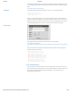
4/27/2018 OpenCR1.0 OpenCR1.0 Back to Top ▲ 6. 1. 5. 2. Install the OpenCR package via Boards Manager Click Tools → Board → Boards Manager. Type OpenCR into the textbox to find the OpenCR by ROBOTIS package. After it finds out, click Install. http://emanual.robotis.
4/27/2018 OpenCR1.0 OpenCR1.0 Back to Top ▲ After the installation, “INSTALLED” will be appeared. See if OpenCR Board is now on the list of Tools → Board. Click this to import the OpenCR Board source. http://emanual.robotis.
4/27/2018 OpenCR1.0 OpenCR1.0 Back to Top ▲ 6. 1. 5. 3. Port setting This step shows the port setting for the program uploads. The OpenCR should be connected to the PC and the OpenCR via the USB ports. Select Tools → Port → /dev/ttyACM0. Warning The last digit value 0 in the string /dev/ttyACM0 might be different depend on the USB connection environment. http://emanual.robotis.
4/27/2018 OpenCR1.0 OpenCR1.0 Back to Top ▲ 6. 1. 6. Remove Modemmanager After programming with the Arduino IDE and uploading the program to the OpenCR, the OpenCR will be restarted and be reconnected. At the same moment, the modem-related packages of the Linux will send the AT command to manage the device. Thus indicates an connection error on the OpenCR, so this step should be done previously. $ sudo apt-get purge modemmanager 6. 1. 7.
4/27/2018 OpenCR1.0 OpenCR1.0 6. 1. 7. 2. Run DFU mode. Back to Top ▲ Press the Reset Button while the Boot Button is being pushed. This activates the DFU mode. If you successfully entered to DFU mode, you will be able to find STMicroelectronics STM Device in DFU Mode text string when lsusb is entered in the terminal. 6. 1. 7. 3. Download the bootloader. Click Tools → Burn Bootloader to download the bootloader. http://emanual.robotis.
4/27/2018 OpenCR1.0 OpenCR1.0 Back to Top ▲ 6. 2. Install on Mac 6. 2. 1. Install Arduino IDE(Mac) Download the latest version of Arduino IDE from the official arduino homepage, and install it. Currently, the OpenCR will be on service in the version 1.6.4 or later. https://www.arduino.cc/en/Main/Software 6. 2. 2. Run Arduino IDE(Mac) To run the Arduino IDE on Mac platform, click the Arduino IDE icon as follows. http://emanual.robotis.
4/27/2018 OpenCR1.0 OpenCR1.0 Back to Top ▲ 6. 2. 3. Porting to Arduino IDE(Mac) 6. 2. 3. 1. Preferences After Arduino IDE is run, click File → Preferences in the top menu of the IDE. When the Preferences window appears, copy and paste following link to the Additional Boards Manager URLs textbox. (This step may take about 20 min.) https://raw.githubusercontent.com/ROBOTIS-GIT/OpenCR/master/arduino/opencr_release/package_ http://emanual.robotis.
4/27/2018 OpenCR1.0 OpenCR1.0 Back to Top ▲ 6. 2. 3. 2. Install the OpenCR package via Boards Manager Click Tools → Board → Boards Manager. Type OpenCR into the textbox to find the OpenCR by ROBOTIS package. Install of the OpenCR package. After the installation, “INSTALLED” will be appeared. See if OpenCR Board is now on the list of Tools → Board. Click this to import the OpenCR Board source. http://emanual.robotis.
4/27/2018 OpenCR1.0 OpenCR1.0 Back to Top ▲ 6. 2. 3. 3. Port setting This step shows the port setting for the program uploads. The OpenCR should be connected to the PC and the OpenCR via the USB ports. Select Tools → Port → /dev/cu.usbmodem1411 Caution The value of /dev/cu.usbmodem1411 may be different depending on the environment connected to the PC. 6. 2. 4. Writing Bootloader(Mac) http://emanual.robotis.
4/27/2018 OpenCR1.0 The STM32F7xx, which is used for the main MCU on the OpenCR board, supports DFU(Device Firmware Upgrade). This enables the built-in bootloader of the MCU by itself to OpenCR1.0 boot the DFU protocol by using USB, primarily for the bootloader initialization, the recovery mode, and the bootloader update. The biggest advantage to let the users be able to use bootloader with USB but no other JTAG equipment.
4/27/2018 OpenCR1.0 OpenCR1.0 Back to Top ▲ 6. 3. Install on Windows 6. 3. 1. Install Driver To use OpenCR’s USB port as a serial port in Windows, you need a USB CDC driver. You can install the USB driver provided by ST. http://www.st.com/en/development-tools/stsw-stm32102.html 6. 3. 2. Install Arduino IDE(Windows) Download the latest version of Arduino IDE from the official arduino homepage, and install it. Currently, the OpenCR will be on service in the version 1.16.0 or later. https://www.arduino.
4/27/2018 OpenCR1.0 OpenCR includes a connector that is compatible with Arduino Uno pinmap. 6. 4. 1. Arduino Connector OpenCR1.0 The pins 0 to 21 are the same pin as the Arduino Uno, and thereafter they are mapped to the pins added to OpenCR. Back to Top ▲ Pin No. Function 1 0 UART RXD UART6_RX 1 UART TXD UART6 TX 2 2 3 EXTI_0 PWM TIM3_CH1 EXTI_1 4 http://emanual.robotis.
4/27/2018 OpenCR1.0 6. 4. 2. User LED The OpenCR additional LEDs consist of four LEDs and are mapped to Arupinopin 22-25. OpenCR1.0 Back to Top ▲ Name Arduino Pin Pin Name USER1 22 BDPIN_LED_USER_1 USER2 23 BDPIN_LED_USER_2 USER3 24 BDPIN_LED_USER_3 USER4 25 BDPIN_LED_USER_4 STS 36 BDPIN_LED_STATUS Arduino 13 LED_BUILTIN 6. 4. 3. Dip Switch Arduino Pin Pin Name 26 BDPIN_DIP_SW_1 27 BDPIN_DIP_SW_2 6. 4. 4.
4/27/2018 OpenCR1.0 OpenCR1.0 Back to Top ▲ Pin Number Arduino Pin Pin Name Pin Number Arduino Pin Pin Name 1 - 3.
4/27/2018 OpenCR1.0 OpenCR1.0 Back to Top ▲ 6. 4. 6. Push Switch Arduino Pin Pin Name 34 BDPIN_PUSH_SW_1 35 BDPIN_PUSH_SW_2 6. 4. 7.
4/27/2018 OpenCR1.0 OpenCR1.
4/27/2018 OpenCR1.0 7. Examples 7. 1. LED It is a built-in LED test on the OpenCR board. OpenCR1.0 7. 1. 1. Code There are 5 LEDs available in OpenCR, USER1 ~ 4, and the LED connected to base 13 of Arduino. USER1 ~ 4 arduino pin numbers are defined as follows. When the corresponding pin is output as High / Low, the LED turns on / off.
4/27/2018 OpenCR1.0 7. 2. Button It is a built-in BUTTON test on the OpenCR board. 7. 2. 1. Code OpenCR1.0 There are Push switches SW1 ~ 2 and Dip switches 1 ~ 2 in OpenCR. The pin number is defined as below, so you can see the status of the current button when you input the data of that pin. #define #define #define #define BDPIN_DIP_SW_1 BDPIN_DIP_SW_2 BDPIN_PUSH_SW_1 BDPIN_PUSH_SW_2 26 27 34 35 It is a code that outputs the button input status in serial. Back to Top ▲ void setup(){ Serial.
4/27/2018 OpenCR1.0 OpenCR has a built-in BUZZER, and the sound varies depending on the frequency. The builtin BUZZER is also mapped to the arduino pin number, and the arduino pin number is as follows. Arduino’s Tone function is ported, so you can use BUZZER by using this function. #define BDPIN_BUZZER 31 OpenCR1.0 It outputs the melody according to the scale defined in the pitches.h header.
4/27/2018 OpenCR1.0 OpenCR1.0 Back to Top ▲ This is an example of PWM output on all six pins. int pwm_pins[6] = { 3, 5, 6, 9, 10, 11 }; void setup() { // put your setup code here, to run once: } void loop() { // put your main code here, to run repeatedly: int i; static uint8_t pwm_out = 0; for( i=0; i<6; i++ ) { analogWrite(pwm_pins[i], pwm_out++); } delay(100); } 7. 4. 2. Result http://emanual.robotis.
4/27/2018 OpenCR1.0 OpenCR Test - PWM OpenCR1.0 Back to Top ▲ 7. 5. EEPROM It is the EEPROM library test of OpenCR board. OpenCR does not have EEPROM memory, so it emulates a part of flash memory built in STM32F746 into EEPROM. The method of emulation was provided by ST as an example. The area used as EEPROM is 0x08010000 ~ 0x08020000 as shown below. Two sectors are used.
4/27/2018 OpenCR1.0 OpenCR1.0 Back to Top ▲ To use the EEPROM library, a header must be added, and the maximum size of the current EEPROM is 1 KBytes. Since the EEPROM library has ported what is supported in Arduino, the basic usage method is the same as that used in other existing Arduino boards. For more information on how to use it, please refer to the Adunion site. https://www.arduino.cc/en/Reference/EEPROM 7. 5. 1. Code #include
4/27/2018 OpenCR1.0 if (Serial.available()) { uint8_t inByte = Serial.read(); if( inByte == '1' { EEPROM.write(0, EEPROM.write(1, EEPROM.write(2, i++; } OpenCR1.0 ) i+1); i+2); i+3); } } 7. 5. 2. Result OpenCR Arduino Test - EEPROM Back to Top ▲ 7. 6. OP3 OpenCR is used for power and sensor control in OP3, a humanoid robot. If the OpenCR firmware for OP3 has been changed, follow the procedure below to update it. 7. 6. 1. Preparations OpenCR develops and downloads firmware through the Arduino IDE.
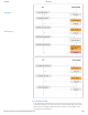
4/27/2018 OpenCR1.0 OpenCR1.0 Back to Top ▲ 5. Click on the icon in the Arduino IDE that displays the red circle in the following figure to build and download the firmware. When the download is completed, the firmware is automatically executed. 7. 6. 3. Editing OP3 Firmware The firmware that is provided as a basic example of OpenCR is read-only. If you want to edit it, you have to save it to a new folder and work on it. 1. Open the OP3 example. http://emanual.robotis.
4/27/2018 OpenCR1.0 OpenCR1.0 Back to Top ▲ 2. Select File-> Save. 3. Since the example provided is Read-Only, select OK to save it as a new file. 4. Save it to a new folder and edit it. Once editing is complete, repeat the process of building and downloading the firmware. http://emanual.robotis.
4/27/2018 OpenCR1.0 OpenCR1.0 Back to Top ▲ 7. 7. Sensors 7. 7. 1. Ambient Light Sensor It is ambient light sensor test on the OpenCR board. Pinouts Green : Signal Red : Vcc Black : Gnd Specification ambient light sensor specification Supply Voltage : 3.3V to 5V Illumination range : 1 Lux to 6000 Lux Interface : Analog 7. 7. 1. 1. Code LED turns off/on sequentially depending on the light received by the sensor. LED turns off in bright place. If it is dark place, the LED turns on.
4/27/2018 OpenCR1.0 { digitalWrite(BDPIN_LED_USER_1, HIGH); digitalWrite(BDPIN_LED_USER_2, LOW); digitalWrite(BDPIN_LED_USER_3, LOW); } else if(analogRead(0)>300 && analogRead(0)<400) { digitalWrite(BDPIN_LED_USER_1, HIGH); digitalWrite(BDPIN_LED_USER_2, HIGH); digitalWrite(BDPIN_LED_USER_3, LOW); } else if(analogRead(0)>400 && analogRead(0)<500) { digitalWrite(BDPIN_LED_USER_1, HIGH); digitalWrite(BDPIN_LED_USER_2, HIGH); digitalWrite(BDPIN_LED_USER_3, HIGH); } Serial.
4/27/2018 OpenCR1.0 tilt sensor and led are connected to OpenCR. so that red/blue led is on/off when tilted and red/blue led is off/on when not tilted. Connect the Tilt Sensor, Led_blue, and Led_red signal pins to D0, D1, and D2. #define tilt 0 #define led_blue 1 #define led_red 2 OpenCR1.
4/27/2018 OpenCR1.0 7. 7. 3. 1. Code Rotation sensor is an analog sensor, the output value depending on the degree of rotation. OpenCR1.0 The LED turned on/off depending on the degree of rotation. The signal pin is connected to A0 of OpenCR. #define #define #define #define BDPIN_LED_USER_1 BDPIN_LED_USER_2 BDPIN_LED_USER_3 BDPIN_LED_USER_4 22 23 24 25 const int analogInPin = A0; int sensorValue = 0; void setup() { Serial.
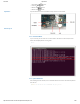
4/27/2018 OpenCR1.0 OpenCR 03 Rotation Sensor Example OpenCR1.0 Back to Top ▲ 7. 7. 4. Capacitive Touch Sensor It is capacitive touch sensor test on the OpenCR board. Pinouts Green : Signal Red : Vcc Black : Gnd Specification Capacitive Touch Sensor Specification Supply Voltage : 3.3V to 5V Interface : Digital 7. 7. 4. 1. Code When you put your hand on the sensor, the led turn on/off sequentially and then the LED turns off when you take your hand.
4/27/2018 OpenCR1.0 { pinMode(SensorINPUT, INPUT); pinMode(BDPIN_LED_USER_1, OUTPUT); pinMode(BDPIN_LED_USER_2, OUTPUT); pinMode(BDPIN_LED_USER_3, OUTPUT); pinMode(BDPIN_LED_USER_4, OUTPUT); } OpenCR1.0 void loop() { if (digitalRead(SensorINPUT) == HIGH ) { for(i=0; i<4; i++) { digitalWrite(LED[i], LOW); delay(100); digitalWrite(LED[i], HIGH); } } if (digitalRead(SensorINPUT) == LOW ) { for(i=0; i<4; i++) { digitalWrite(LED[i], HIGH); } } } Back to Top ▲ 7. 7. 4. 2.
4/27/2018 OpenCR1.0 Supply Voltage : 3.3V to 5V Interface : Analog 7. 7. 5. 1. Code OpenCR1.0 If the flame is detected, turns on the led. Fire near the sensor, it outputs a high value close to 1024. If the output exceeds 800, led will turn on. Signal is connected to A0 of Arduino. #define BDPIN_LED_USER_1 22 #define flame 0 void setup() { Serial.
4/27/2018 OpenCR1.0 OpenCR1.0 Specification Joystic Sensor Specification Interface : Analog Back to Top ▲ 7. 7. 6. 1. Code Joystic is to get the output value according to the input. We will look at the X Y Z values that change depending on how we move. Signal of x,y and z is connected to A0, A1, A2 of Arduino. #define X A0 #define Y A1 #define Z A2 void setup() { Serial.begin(9600); } void loop() { int x,y,z; x=analogRead(X); y=analogRead(Y); z=analogRead(Z); . Serial.print(" X = "); Serial.
4/27/2018 OpenCR1.0 OpenCR 05 Joystic Example OpenCR1.0 Back to Top ▲ 7. 8. Dynamixel Workbench 7. 8. 1. Find Dynamixel When you get a Dynamixel first, you need to know what ID and Baud rate is. This example find out ID and Baud rate of connected Dynamixels. begin function set PortHandler and PacketHandler. scan function ping all Dynamixels. After get Dynamixels, you can check ID and Baudrate of its.
4/27/2018 OpenCR1.0 for (int i = 0; i < dxl_cnt; i++) { Serial.println(" id : " + String(scanned_id[i]) + " } Model Name : " + String(dxl_wb.g index++; } Serial.println("End"); OpenCR1.0 } void loop() { } 7. 8. 2. Position Back to Top ▲ This example shows position control using Dynamixel. You need to set parameters of BAUDRATE and ID. begin function set an portHandler and packetHandler. ping function get an item of connected Dynamixel. jointMode function make joint(position) mode.
4/27/2018 OpenCR1.0 7. 8. 3. Speed This example shows velocity control using Dynamixel. You need to set parameters of BAUDRATE and ID. begin function set an portHandler and packetHandler. ping function get an item of OpenCR1.0 Back to Top ▲ connected Dynamixel. wheelMode function make wheel(velocity) mode. If Dynamixel is set correctly, goalSpeed function make it turn to position. /******************************************************************************* * Copyright 2016 ROBOTIS CO., LTD.
4/27/2018 OpenCR1.0 8. Downloads Download BOM Download Schematic PCB Download OpenCR1.0 9. References 9. 1. Recovery Mode e-Manual OpenCR Firmware Recovery Back to Top ▲ © 2018 ROBOTIS. Powered by Jekyll & Minimal Mistakes. http://emanual.robotis.