
Data Sheet

16
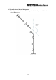
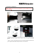
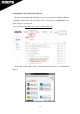
2.3 Installation of Manipulator
The content below is based on an optional base plate and differs from the
actual base plate.
- Rest and fix joint 1 of the manipulator.
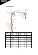
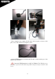
- The photo on the left is the external wiring for the arm. Label “1” shows a pair of
4P cables and power connector; these connect to joint 1 as shown on the right
picture.
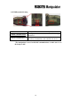
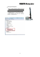
- Label “2” shows a 4P connector and 4 power connectors and these connect to the
power expansion hub and the 4P cable connects to the extension.