ROBOTIS Manipulator SDK User Manual
Contents 1. Introduction 1.1 1.2 1.3 1.4 1.5 1.6 1.
1. Introduction 1.1 About this document ⅰ) This manual applies to the Dynamixel PRO-based Robotis Manipulator. ⅱ) All parameters in this manual are based on default values. ⅲ) The manipulator’s configuration is provided. The ArmSDK is based on Windows7 and Visual Studio 2010. ⅳ) It is strongly recommended with proficiency with Dynamixel PRO and C++. ⅴ) The units utilized in the ArmSDK are in radians (rad) and millimeters (mm).
1.2 Safety DANGER! Information appearing in a DANGER concerns the protection of personnel from the immediate and imminent hazards that, if not avoided, will result in immediate, serious personal injury or loss of life in addition to equipment damage. - Keep away from the robot while its moving.. - Do not touch with the robot with wet hands. - Turn off power of the robot whenever robot is problematic.
1.
1.
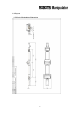
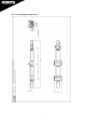
ii) L Series Manipulator Dimension 7
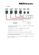
ii) Wiring - The diagram above illustrates joints 1~6 connected in daisy-chain (serial) configuration with 4P Cable. - Joint 1 (labeled as “1st”) connects to USB2Dynamixel via 4P Cable. - USB2Dynamixel connects to PC via USB hub. - Dynamixel Pro is powered from a a power supply via power expansion hub. - Joints 5 and 6 (model: L42 - 10 - S300 – R) are not separately powered; instead power comes from the same 4P Cable. - You may obtain more 4P or Power Cables via ROBOTIS or see section 2.
1.
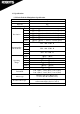
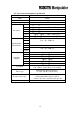
ii) L Series Robotis Manipulator Specification Item Description DOF 6 DOF Payload 1kg Operating voltage 24V Joint 1 - (rad) ~ (rad) → -125700 ~ 125700 (pulse) Joint 2 - (rad) ~ (rad) → -125700 ~ 125700 (pulse) Joint 3 - (rad) ~ (rad) → -125700 ~ 125700 (pulse) Resolution Joint 4 - (rad) ~ (rad) → -144180 ~ 144180 (pulse) Joint 5 - (rad) ~ (rad) → -2048 ~ 2048 (pulse) Joint 6 - (rad) ~ (rad) → -2048 ~ 2048 (pulse) Joint 1 Joint 2 L54 – 50 – S500 - R Dynamixel Pro Joint 3 Model Name Joint 4 L54 – 30 – S500 -
1.6 D-H Configuration DH Parameter Link No. Link Length (mm) 1 0 2 Link Twist (rad) - 265.
1.7 Home Position of Robotis Manipulator - The diagram below shows the “home position” of the Dynamixel PROs from Robotis Manipulator.
2. Getting Started 2.1 Prerequisites ⅰ) The ArmSDK is based on Window 7 OS and Visual Studio 2010. ⅱ) The ArmSDK trajectory is generated from the MotionPlay class’ instance and utilizes QueryPerformanceCounter. This requires the use of a thread, in which sharing said thread may reach to 100%. It is highly recommended your PC is at least dual-core-based. ⅲ) The Numerical IK implements Damped Least Square Method to reach target by acquiring each joint’s angle.
2.2 Preparation ⅰ) Power Supply The manipulator requires 24V for operations. Ensure the power supply is capable of supplying 24V and 15A or higher. ⅱ) 4P Cable The 4P Cable connects the manipulator and USB2Dynamixel. 4P Cable connector Pin array 1 2 3 4 GND VDD DATA + DATA - cable PCB Header Cable (Housing) Cable (Terminal) Connector specifications MOLEX 22-03-5045 MOLEX 50-37-5043 MOLEX 08-70-1039 ⅲ) Power Cable The power cable supplies power to the manipulator.
ⅳ) USB2Dynamixel The USB2Dynamixel sends ArmSDK commands to the manipulator. Connect the USB2Dynamixel to the PC via USB hub.
2.3 Installation of Manipulator The content below is based on an optional base plate and differs from the actual base plate. - Rest and fix joint 1 of the manipulator. - The photo on the left is the external wiring for the arm. Label “1” shows a pair of 4P cables and power connector; these connect to joint 1 as shown on the right picture. - Label “2” shows a 4P connector and 4 power connectors and these connect to the power expansion hub and the 4P cable connects to the extension.
- Once connections are complete fix the arm to the base plate as shown on the photo above. The joint fixed to the plate is joint 1. - Connect USB2Dynamixel to the hub with 4P cable; connect another port of the 4P hub to the extension. Connect the USB2Dynamixel to the PC via USB hub. The USB hub acts as an isolator to protect the PC from any possible unexpected surges caused by arm action.
2.4 USB2Dynamixel Setting 1. TTL communications 2. RS485 communications 3. RS232 communications AX, 3-pin MX; communicate with 3-pin Dynamixel RX, 4-pin MX and Pro; communicate with 4-pin Dynamixel. CM-5and CM-510; communicate with these controllers. Communicate with other RS-232 devices. The manipulator is based on RS-485 communications so make sure to set the dongle to 485.
2.5 Manipulator Test on Dynamixel Wizard - Test the arm with Dynamixel Wizard to check for any anomalies. DynamixelWizard is included in RoboPlus suite. RoboPlus can be downloaded from ROBOTIS home page’s 'Support -> Downloads. (do not download RoboPlus v2.0. instead, get RoboPlus v1.0). - Install and run RoboPlus; click on Dynamixel Wizard button to start Dynamixel Wizard.
ⅰ) Moving the Manipulator - Before starting Dynamixel Wizard ensure the arm is fixed to the base plate; then extend the arm. Otherwise; it may cause physical harm. - USB2Dynamixel to the PC after wiring is complete. From the PC check the COM port number of USB2Dynamixel.
- select the Port Settings tab and click on the Advanced button-> change the latency time from 16 (default) to 1. - After changing the COM port settings supply the 24V to the arm (of course, this means wiring is complete). Always ensure before powering on. While power is on du not change wires; otherwise it may cause undesired operations.
- The picture on the left is the COM port number of USB2Dynamixel (which should be connected to the arm). Click on the to continue. - Once connected make sure that 1000000bps box is checked and “DXL 2.0” is selected. Then click on Search. The arm’s default baud rate is 1 Mbps.
- Once search is complete the arm’s components (Dynamixel PROs) are listed on the left. Click on an individual Dynamixel PRO to display the contents of its Control Table. - Dynamixel Pro will only move (operate) when Torque Mode is on. So always make sure the Torque Mode is on prior to sending moving commands. Torque Enable is located on address number 562. A value of 1 means on and 0 means off.
- Turn ‘Torque Enable’ on to all joints. The pose of the arm will become rigid (check by applying a small force). Afterwards click on joint 6. - now verify the arm moves properly by changing Goal Position. Move the end effector (joint 6) +90 degrees. To move joint 6 to +90 degrees set Goal Position of the Dynamixel PRO model H42-20-S300-R to 75938 or L42-10-S300-R to 1024. - once Goal Position has been set visually verify that joint 6 has rotated 90 degrees.
- click on ID. Set the Goal Position to 1000 (500 for L42 model). - to actually get Dynamixel PRO to move to its respective Goal Position click on the Apply button after setting the value. If no movement happen make sure Torque Enable is turned on (set to 1). - Set Goal Position back to 0 to set position to its original position.. - do the same procedure for joint 2 through 6.
ⅱ) Goal Position values with respect to rotation - Goal Position value determines the rotational position of Dynamixel PRO.
-180 ~ 180 (deg) → -144180 ~ 144180 L54-30-S500-R -180 ~ 180 (deg) → -2048 ~ 2048 L42-20-S300-R 27
2.6 How to use Robotis Manipulator SDK ⅰ) Preparation Before using Robotis Manipulator SDK The following are pre-requisites for the ArmSDK. Eigen Package( http://eigen.tuxfamily.org, version 3.0.6 or Later) ⅱ) Installation Package - Download and unzip Eigen Package. - Start Visual Studio go to “Project Properties -> VC++ Directories -> Include Directories” set Eigen’s source directory.
- repeat procedure (i)~(ii) to include the examples and include directories. - once preparations are complete press the F7 key to compile and build.
3. Examples The following examples are included with the ArmSDK; ArmMonitor01, ArmMonitor02, SimpleP2P, SimpleIK, and SimpleTorqueOnOffandFK. 3.1 ArmMonitor In ArmMonitor allows viewing of a joint current position, target position, end effector’s pose, and joint paramenters (Velocity, Acceleration, Position P, I, D Gain, Velocity P, I Gain). Change the values from the table below to see changes.
ⅰ) How to Use ArmMonitor (1) ArmMonitor01 - To start ArmMonitor01 create a new project; once created press the Ctrl + F5 keys to run.
You will need to enter the COM port number and baud rate. Simply enter the values and “Succeed to open USB2Dynamixel” should appear onscreen followed by “Press any key to move first pose.” Use the keyboard to move the arm. The following table is the list of baud rate values and its corresponding speed; Robotis Maniupulator default value is 3 (1Mbps).
Press the Ctrl + F5 keys simultaneously and the screen should appears like the picture above From ArmMonitor01 change the joint’s target position and joint parameter to move the arm. Use the directional keys to move cursor. Use the ‘[’ ‘{’ keys to lower values and ‘]’ ‘}’ to increase. From the picture (from the screen output) with the red area with “1” it shows the joints current pose (Present Value) and end effector’s pose. The red area with “2” shows the target pose (Goal Value) for all joints.
The Goal Value of Arm의 Calc value (enclosed by the red frame) can be increased with the‘]’ key. The unit is Visually verify arm movement every time when changing position.
(2) ArmMonitor02 Use of this example may pose safety risks. When testing the example keep a safe distance while able to cut power off in case of undesired operation. ArmMonitor02 allows direct control of the end effector. Control the end effector is done by ComputeIK function where it moves each joint to its solution position (rad).
To setup and run ArmMonitor02 follow the same procedure as in ArmMonitor01. As in ArmMonitor01 you will be asked to enter COM port number and baud rate. You should also see “Succeed to open USB2Dynamixel” followed by “Press any key to move first pose.” The arm moves to its initial pose. The photo below is the arm in its “arrival” pose.
The different values of the end effector depicted from the red areas with “1” and “2” (from the screen output image above) is due to the difference of Dynamixel Pro’s Goal Position and Present Position values (gear backlash) and DH with the point of origin. 1”1” shows the end effector’s pose via calculations from kinematics and “2” the actual pose. Press the ] key to increase the end effector’s pose value by increases by 2mm. Visually verify arm movement every time when changing position.
ⅱ) Arm Monitor Source Description (1) cmd_process.
- void MoveUpCursor() - void MoveDownCursor() - void MoveLeftCursor() - void MoveRightCursor() these 4 functions allows the directional keys to control cursor location..
- void initialize(void) initialize() function described below. gpArmComm = new Pro_Arm_Comm_Win() gpArmComm is a class of Pro_Arm_Comm_Win. Pro_Arm_Comm_Win includes ID and baud num-related aspects.
gpArmKinematics->SetConvergenceCondition(0.001, 5.0) sets convergence for IK. 1st value to determine solution; second value maximum allowed. gvdGoalCalculationAngleRad.resize(gpRobotisArm->GetRobotInfo()->size()) setup target pose value (rad). gvdRealCalculationAngleRad.resize(gpRobotisArm->GetRobotInfo()->size()) current pose value (rad). gvdGoalDynamixelAngleRad.resize(gpRobotisArm->GetRobotInfo()->size()) target joint’s position value (rad) gvdRealDynamixelAngleRad.
gviVelocityPGain.resize(gpRobotisArm->GetRobotInfo()->size()) Velocity P Gain value. gviVelocityIGain.resize(gpRobotisArm->GetRobotInfo()->size()) Velocity I Gain value. gviDynamixelVelocity.resize(gpRobotisArm->GetRobotInfo()->size()) Velocity value. gviDynamixelAcceleration.
Position P, I, D Gain functions. Default P gain value is 64 이고; I and D Gain are 0. the .fill contains every joint’s PID values individually. gpArmComm->Arm_Torque_On(); This function gets initialized before moving the arm to its initial pose. gpArmComm->Arm_Set_Position_PID_Gain(DEFAULT_POSITION_P_GAIN, DEFAULT_POSITION_I_GAIN, DEFAULT_POSITION_D_GAIN); Sets the manipulator joints’ PID gain values..
_tempMotionTimer.Start(); gvdGoalCalculationAngleRad = gpMotionPlayer->NextStep(&ErrorStatus); gvdGoalDynamixelAngleRad = gvdGoalCalculationAngleRad + gvdAngleGapCalcandDynamixelRad; gviGoalDynamixelAngleUnit = gpRobotisArm ->Rad2Value(gvdGoalDynamixelAngleRad); CommResult = gpArmComm ->Arm_Set_JointPosition(gviGoalDynamixelAngleUnit); gvdGoalCalculationAngleRad = gpMotionPlayer->NextStep(&ErrorStatus) gvdGoalDynamixelAngleRad = gvdGoalCalculationAngleRad + gvdAngleGapCalcandDynamixelRad _tempMotionTimer.
Position Value is set again with Rad2Value, the resulting Arm_Set_JointPosition moves the manipulator. If successful , the manipulator’s communications Arm_Set_JointPosition returns a value of 1. gvdRealDynamixelAngleRad = gpRobotisArm->Value2Rad(gviRealDynamixelAngleUnit); gvdRealCalculationAngleRad= gvdRealDynamixelAngleRad - gvdAngleGapCalcandDynamixelRad; After motion is complete it print’s the joint’s actual pose(rad) and calculated pose(rad).
3.2 SimplePtoP Product may move fast with this example. When testing this example keep a safe distance while able to cut power off in case of undesired operation SimplePtoP is the end effector’s move point (from P1 to P2). ⅰ) How to Use SimplePtoP To start SimplePtoP follow the same procedure for ArmMonitor. Then press the Ctrl + F5 keys to run. You will be asked for COM port number and baud rate. If succeded then you will see a ‘Succeed to open USB2Dynamixel’ followed by ‘Press any key to move first pose.
SimplePtoP displays the joints’ pose(rad). In SimplePtoP prssing the 'p' or ‘P' will cause motion to pause. Press the ESC key to end.
ⅱ) SimplePtoP Source Description vecd P1, P2; P1.resize(RobotisArm.GetRobotInfo()->size()); P2.resize(RobotisArm.GetRobotInfo()->size()); P1, P2 sets every joint’s position. P1.fill(0.0); P1 -= gvdAngleGapCalcandDynamixelRad; P2.fill(0.5); P2 -= gvdAngleGapCalcandDynamixelRad; P1.fill, P2.fill input every joint’s position(rad) individually. Differences between DH Configuration’s point of origin and actual point of origin are taken into consideration so P1 and P2 are to be adjusted accordingly. ArmComm.
ArmTrajectory.Set_P2P(P2, P1, 10.0, 0.5); sets P1, P2(Start, EndPose). In this case P1 is 0.0 rad and P2 is 0.5 rad. Trajectory is from P2 to P1 MotionPlayer.All_Info_Reload(); MotionProfile calls Info(Robot, Kinematics, Trajectory). MoionPlayer.Initialize(); MotionProfile, Step, are initialized. MotionPlayer.Set_Time_Period(DEFAULT_Ctrl_TIME_PERIOD); sets time period. For value lesser than 0 then a default value (=8) gets inputted.
3.3 SimpleIK Use of this example may pose safety risks. When testing the example keep a safe distance while able to cut power off in case of undesired operation. Allows operation of end effector’s pose via position(X, Y, Z) and orientation(Roll, Pitch, Yaw). The keys for SimpleIK are q, w, e, r, t, y and a, s ,d ,f, g, h.
ⅰ) How to Use SimpleIK To start SimpleIK start a new project just like SimplePtoP. Then press the Ctrl + F5 ekys to begin. In SimpleIK you will be asked for COM port and baud rate numbers. If succeeded you will see a 'Succeed to open USB2Dynamixel' followed by ‘Press any key to move first pose.' Press a key to begin. The arm moves to its initial pose as shown below.
This windows pops up after the arms moves to its initial pose. The values printed are the joints’ angles(rad). Press the keys(ex : q, w....) to move the end effector. SimpleIK q key control the 3rd value. Q controls the end effector position (X) by increasing delta(5mm)amounts. Visually verify arm movement every time when changing position.
Press the q and r keys 3 times each. The r key controls the end effector’s roll. The orientation (Roll, Pitch, Yaw) change by per keystroke. Visually verify arm movement every time when changing position.
ⅱ) SimpleIK Source Description if(temp == 'q') { DesiredPose = CurrentPose; DesiredPose.x += delta; ArmKinematics.ComputeIK(DesiredPose, &angle_rad, angle_rad, &ErrorStatus); if(ErrorStatus == ARMSDK_NO_ERROR) { cout<<"Answer"<
The code shows that by pressing the q key the program runs. A press of q moves the end effector pose in the (X) coordinate by delta (5mm). If there are no errors the end effector will move according to keystroke. All joints are in radians. Press the 'q‘ key to to goal pose by X position in delta incrememts. Despite having errors and not being able to get the IK moving can be allowed.
ArmKinematics.Forward(angle_rad, &CurrentPose); Once moved to desired pose angle_rad(array) gets the end effector’s pose and runs forward kinematics; then CurrentPose sets the pose. This function returns the end effectors transform matric (4x4).
else if(temp == 'r') { DesiredPose = CurrentPose; matd DesiredRotation = Algebra::GetOrientationMatrix(delta_angle_rad, 0.0, 0.0) * Algebra::GetOrientationMatrix(CurrentPose.Roll, CurrentPose.Pitch, CurrentPose.Yaw); vecd DesiredRPY = Algebra::GetEulerRollPitchYaw(DesiredRotation); DesiredPose.Roll = DesiredRPY(0); DesiredPose.Pitch = DesiredRPY(1); DesiredPose.Yaw = DesiredRPY(2); ArmKinematics.
The goal pose runs IK my moving the roll gets increased by delta(rad). The end effector moves to whatever the IK has solved and displays the joint poses(rad). Despite having errors and not being able to get the IK moving can be allowed. If 'Do you want make the Robot move? (Y/N)' appears onscreen press the y key to turn the end effector in the roll axis by delta_angle_rad. Then the joints pose(rad) are displayed.
3.4 SimpleTorqueOnOffandFK Turns the manipulator joints’ torque on/off. When torque goes off→on Forward Kinematics runs and putputs all joints pose(rad) and end effector’s position and orientation. ⅰ) How to Use SimpleTorqueOnOffandFK To start SimpleTorqueOnOffandFK start a new project just like SimplePtoP. Then press the Ctrl+F5 keys to begin.SimpleTorqueOnOffandFK. Input the COM port and baud rate numbers. If succeeded you will see a 'Succeed to open USB2Dynamixel;' then torque gets turned off.
Press Enter again to turn torque off and it will display 'Torque Off.' Press the Enter key once again to turn torque on and the values be displayed again.
ⅱ) SimpleTorqueOnOffandFK Source Description while(true) { char temp = _getch(); if(temp == 27) break else if(temp == 13) { if(gbArmTorque) { ArmComm.Arm_Torque_Off(); std::cout<<"Torque Off"<
on and off, When torque gets turned on the joints and end effector pose get outputted onscreen. This happens with every “on” state. Press the Esc key then Enter key and the arm remains as is. The sample code from above is broken down below. The joint angles and Dynamixel angles may not be the same so it must be taken into consirderation. Angle of Dynamixel is the output of the actual angle of Dynamixel.
4. Robotis Manipulator SDK Programming 4.
4.2 Description for Robotis Maniupulator SDK ⅰ) RobotInfo When making them anipulator’s build RobotInfo class’s Addjoint generated instance. AddJoint gets values from D-H Parameter and actuator’s max and min turn angle in rad and value as well as actuator ID number (min and max turn angles may not be the same as joint angle limits). ⅱ) Kinematics Forward Kinematics(FK), Inverse Kinematics(IK) can be calculated once the instance for kinematics class is generated.
ⅲ) Trajectory Generating The TrajectoryGenerator class generates an instance for the arm’s trajectory. The SDK’s Point to Point, Linear, and Circular can generate a trajectory. For arm-only trajectory then only Set_PTP, Set_LIN, Set_Circular; for the gripper then Set_PTPwithHand, Set_LINwithHand, Set_CIRCwithHand. ⅳ) Velocity Profile The SDK’s Velocity Profile does not take max velocity and max acceleration into consideration in the Trapezoidal Velocity Profile.
ⅴ) Set_PTP The Set_PTP function determines 2 poses for the manipulator (initial and final) by factoring in Trapezoidal Velocity Profile and receives velocity time and total time. Initial and final pose are in rad and joint angle in mm or rad (x, y, z, roll, pitch, yaw). When generating the trajectory it is recommended to factor in joint angles. ⅵ) Set_LIN The Set_LIN function generates a 3-point coordinates for the robot’s straight trajectory.
ⅶ) Set_CIRC The Set_CIRC function generates a 3-point coordinates for the robot’s circular trajectory. This factors in initial and final pose. It sets a point of origin in the area and proceeds to trajectory via MotionPlay and vector generation.
ⅷ) Trajectory Following When moving by the generated trajectory from TrajectorGenerator class’s instance just use NextStep function from MotionPlay. MotionPlay class accounts trajectoryGenerator class. The control period from MotionPlay default value is 8ms but can be changed with SetTimePeriod. If TimePeriod is 0 then 8ms default value is applied. ⅸ) Pro_Arm_Comm_Win Pro_Arm_Comm_Win utilizes DYNAMIXEL 2.0 Protocol from the Windows version of DYNAMIXEL SDK.
5. Maintenance 5.1 Restore Firmware When Dynamixel detection fails ensure is properly wired. If problems perists restore Dynamixel firmware (shown below). After firmware restoration you will need to set ID and baud rate values again. Always make sure to set USB2Dynamixel switch to “485.” ⅰ) restoring firmware - From Dynamixel Wizard click on the icon to begin. - select the corresponding COM port number for USB2Dynamixel. ⅱ) Firmware restore process steps explained.
ⅳ) pick the COM port number - with an incorrect number Dynamixel cannot be automatically detected. Always make sure to get the port number right. - click on Search.
ⅵ) Upon successful detection the Next button is clickable . ⅶ) Pick the right model - pick the right type from the list. If not it may result in problems . ⅷ) during restoration - while restoring the LED will blink. Do not cut power off during this stage.
All Control Table settings are set to default values.
6. Reference 6.1 ARMSDK_Definitions (1) Pose3D Data Fields double x, y, z double Roll, Pitch, Yaw Description Position(x,y,z) and Orientation(Roll, Pitch, Yaw) elements (2) timeprofile Data Fields double ta, tc, td, totaltime double a0[3], a1[3], a2[3] double distance, distance1 int Method Description Trapezoidal Velocity Profile’s elements distance1 only used in circular trajectory.
6.2 ARMSDK_Math.
6.3 MotionEngine ⅰ) Error.h (1) void ErrorCheck(int Error) Parameter int Error Return void 1. no error (ARMSDK_NO_ERROR 0x00) 2. IK solution does not exist (ARMSDK_NO_IK_SOLUTION 0x01) 3. no IK solution and allowable error Description (ARMSDK_ACCEPTABLE_ERROR 0x02) 4. Joints’ next and previous step large difference in angle (ARMSDK_TOO_MUCH_ANGLE_CHANGE 0x04) 5.
ⅱ) JointData.h (1) void SetJointID(unsigned int ID) Parameter unsigned int ID Return void Description Assign Joint ID (2) void SetJointAngle(double JointAngle); Parameter double JointAngle Return void Description Set Joint Angle (3) void SetMinAngleInRad(double MinAngleInRad); Parameter double MinAngleInRad Return void Description Set actuator min angle(rad) Value utilized in 6.
(6) void SetMaxAngleInValue(int Max_AngleValue); Parameter int Max_AngleValue Return void Set actuator max value Description Utilized in 6.
(11) double GetJointAngle(void); Parameter void Return double current Angle Description Returns joint angle limit(rad) (12) double GetMinAngleInRad(void); Parameter void Return MinAngle(rad) of Actuator Description SetMinAngleInRad returns actuator min angle(rad) (13) double GetMaxAngleInRad(void); Parameter void Return MaxAngle(rad) of Actuator Description SetMaxAngleInRad returns actuator max angle(rad) (14) int GetMinAngleInValue(void); Parameter void Return MinAngle(value) of Ac
(16) double GetMinAngleLimitInRad(void); Parameter Void Return MinAngle(rad) of Joint Description SetMinAngleLimitInRad returns joint min angle(rad) (17) double GetMaxAngleLimitInRad(void); Parameter void Return MaxAngle(rad) of Joint Description SetMaxAngleLimitInRad returns joint max angle(rad) (18) int GetMinAngleLimitInValue(void); Parameter void Return MinAngle(value) of Joint Description SetMinAngleLimitInRad returns joint min angle(value) (19) int GetMaxAngleLimitInValue(void);
ⅲ) RobotInfo.
Parameter void Return ID List of Robot Actuators Description Returns joint ID in aray form inAddJoint (6) veci Rad2Value(vecd q); Parameter double array of Actuators Angle(Rad) Return int array of Actuators Angle(Value) Description Transforms joint’s rad to value. (7) vecd Value2Rad(veci q); Parameter int array of Actuators Angle(Value) Return double array of Actuators Angle(Rad) Description Transforms joint’s value to rad.
ⅳ) Kinematics.
(5) void SetConvergenceCondition(double max_error, double max_acceptable_error); Parameter double max_error, double max_acceptable_error Return void IK’s amount of telorable error. The first input value is max convergence error. A lesser value Description than max can allow solution. The second value is max allowable error; acceptable as long as is lower than value entered. When value exceeds then there is no solution..
(8) void ComputeIK(Pose3D _desired , vecd *q_rad, vecd Initangle_rad, int *ErrorStatus); Parameter Pose3D goalPose, vecd initangle, int ErrorStatus Return void Description get jacobian’s Damped Least Square Method for IK solution _desired is end effector’s desired pose *q_rad sets joints pose after running IK Initangle_rad is joint angles prior to running IK *ErrorStatus is pointer for error type ErrorStatus. 1. no error (ARMSDK_NO_ERROR 0x00) 2. No solution from IK (ARMSDK_NO_IK_SOLUTION 0x01) 3.
ⅴ) TrajectoryGenerator.
(5) void Set_LIN(Pose3D StartPose, Pose3D EndPose, double TotalTime, double AccelTime) Parameter Pose3D StartPose / Pose3D EndPose double TotalTime / double AccelTime Returns void Description Sets linear trajectory from StartPose, EndPose, TotalTime, AccelTime.
(9) void Set_P2PwithHand(Pose3D StartPose, Pose3D EndPose, veci Hand1, veci Hand2, double TotalTime, double AccelTime) Parameter Pose3D StartPose / Pose3D EndPose veci Hand1 / veci Hand2 double TotalTime / double AccelTime Returns void Description Sets P2P trajectory from StartPose, EndPose, Start HandPose, End HandPose, TotalTime, AccelTime (10) void Set_LINwithHand(vecd StartPose, veci Hand1, vecd EndPose, veci Hand2, double TotalTime, double AccelTime) Parameter vecd StartPose / vecd EndPose
(12) void Set_CIRCwithHand(vecd StartPose, vecd ViaPose, vecd EndPose, veci Hand1, veci Hand2, double TotalTime, double AccelTime) Parameter vecd StartPose / vecd EndPose / vecd ViaPose veci Hand1 / veci Hand2 double TotalTime / double AccelTime Returns void Description Sets circular trajectory from StartPose, ViaPose, EndPose, Start HandPose, End HandPose, TotalTime, AccelTime (13) void Set_CIRCwithHand(Pose3D StartPose, Pose3D ViaPose, Pose3D EndPose, veci Hand1, veci Hand2, double TotalTime
ⅵ) MotionPlay.
(6) vecd CalcIK(Pose3D desiredPose, int *ErrorStatus) Parameter Pose3D desiredPose / int * ErrorStatus Returns Joint Angle of desiredPose Description Returns desired pose of end effector via IK *ErrorStatus is pointer for error type 1. no error (ARMSDK_NO_ERROR 0x00) 2. No solution from IK (ARMSDK_NO_IK_SOLUTION 0x01) 3. no solution from IK, allowable error (ARMSDK_ACCEPTABLE_ERROR 0x02) 4.
(10) Pose3D GetCurrentEndPose(void); Parameter void Returns Pose3D of EndEffector Description Returns end effector’s current pose (11) double Get_CurrentTime(void); Parameter void Returns double CurrentTime Description Returns current time 91
6.4 RobotisLib ⅰ) Pro_Arm_Comm_win.
(6) int Arm_Torque_On(void); Parameter void Returns Communication Result Description Turn torque on every joint COMM_RXSUCCESS return of 1 (7) int Arm_Torque_Off(void); Parameter void Returns Communication Result Description Turns torque off on every joint COMM_RXSUCCESS return of 1 (8) int Arm_Set_JointPosition(veci position); Parameter joint angle array Returns Communication Result Description Sets joint angles COMM_RXSUCCESS return of 1 (9) int Arm_Set_JointVelocity(veci velocity);
(11) int Arm_Set_JointAcceleration(veci accel); Parameter int joint Acceleration array Returns Communication Result Description Sets joint accelerations COMM_RXSUCCESS return of 1 (12) int Arm_Set_JointAcceleration(int accel); Parameter int joint Acceleration Returns Communication Result Description Sets joint accelerations COMM_RXSUCCESS return of 1 (13) int Arm_Set_Position_PID_Gain(int P_Gain, int I_Gain, int D_Gain); Parameter int joint Position P, I, D gain Returns Communication Result
(16) int Arm_Get_JointCurrent(veci *torque); Parameter joint current array Returns Communication Result Description Reads joint’s electrical current flow and saves in (*torque) return pointer COMM_RXSUCCESS return of 1 (17) int Arm_LED_On(void); Parameter void Returns Communication Result Description Turns joints’ LED on COMM_RXSUCCESS return of 1 (18) int Arm_LED_Off(void); Parameter void Returns Communication Result Description Turns joints’ LED off COMM_RXSUCCESS return of 1 (19) int
(23) void Gripper_ID_Setup(veci Gripper_ID_List); Parameter ID array Returns void Description Sets ID for gripper.
6.5 Timer ⅰ) MotionTimer.