© ROBOTIQ INC. 2014 Get the latest version of the manual at support.robotiq.
Table of Contents Revisions . . . . . . . . . . . . . . . . . . . . . . . . . . . . . . . . . . . . . . . . . . . . . . . . . . . . . . . . . . . . . . . . . . . . . . . . . . . . . . . . . . . . . . . . . . . . . . . . . . . . 1. General Presentation . . . . . . . . . . . . . . . . . . . . . . . . . . . . . . . . . . . . . . . . . . . . . . . . . . . . . . . . . . . . . . . . . . . . . . . . . . . . . . . . . . . . . . . . . 2. Safety . . . . . . . . . . . . . . . . . . . . . . . . . . . . . . . . . . . .
Robotiq 3-Finger Adaptive Robot Gripper Instruction Manual Revisions Robotiq may modify this product without notice, when necessary, due to product improvements, modifications or changes in specifications. If such modification is made, the manual will also be revised, see revision information. See the latest version of this manual online at http://support.robotiq.com/.
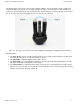
Robotiq 3-Finger Adaptive Robot Gripper Instruction Manual 1. General Presentation The terms "Gripper", "Adaptive Gripper", "Robotiq Gripper" , "S-Model", "3-Finger Gripper" and "Robotiq Adaptive Gripper" used in the following manual all refer to the Robotiq 3-Finger Adaptive Robot Gripper. The Robotiq 3-Finger Adaptive Robot Gripper is a robotic peripheral that is designed for industrial applications.
Robotiq 3-Finger Adaptive Robot Gripper Instruction Manual Two different types of movements can be performed with the Gripper. The first determines the type of grip being used and simultaneously changes the orientation of Fingers B and C as shown in Figure 1.2. This movement is referred to as the 'Operation Mode'. The Operation Mode is determined by the user prior to the grip as a function of the size or shape of the object being gripped and for the task that has to be done. Figure 1.
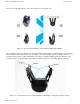
Robotiq 3-Finger Adaptive Robot Gripper Instruction Manual The four pre-set Operation Modes can be chosen by the user (see Figure 1.3). Figure 1.3 : The four Operation Modes of the 3-Finger Adaptive Robot Gripper. The second movement of the Gripper is the closing and opening of the fingers as shown in Figure 1.4. This action is performed with a single input from the user.
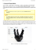
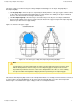
Robotiq 3-Finger Adaptive Robot Gripper Instruction Manual Two types of grips occur when closing the 3-Finger Adaptive Robot Gripper on an object: Fingertip Grip or Encompassing Grip. The Fingertip Grip is when an object is only held by the distal phalanxes. This type of grip is similar to what is done with conventional industrial parallel grippers. In this situation, the stability of the grip is maintained because of the friction between the fingers and the object.
Robotiq 3-Finger Adaptive Robot Gripper Instruction Manual Info Operation Modes are inputs to the Gripper. Whether the fingers close to produce an Encompassing or Fingertip grip is decided at the Gripper level automatically . It will depend on: The Operation Mode; The part's geometry; The relative position of the part with respect to the Gripper.
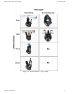
Robotiq 3-Finger Adaptive Robot Gripper Instruction Manual Figure 1.6 : Operation Modes vs. Types of Grip. Robotiq inc.
Robotiq 3-Finger Adaptive Robot Gripper Instruction Manual 2. Safety Warning The operator must have read and understood all of the instructions in the following manual before handling the Robotiq 3-Finger Adaptive Robot Gripper.
Robotiq 3-Finger Adaptive Robot Gripper Instruction Manual 2.1 Warning Note Any use of the Gripper in noncompliance of these warnings is inappropriate and may cause injury or damage. Warning The Gripper needs to be properly secured before operating the robot. Do not install or operate a Gripper that is damaged or lacking parts. Never supply the Gripper with an alternative current source. Make sure all cord sets are always secured at both ends, at the Gripper and at the robot.
Robotiq 3-Finger Adaptive Robot Gripper Instruction Manual 2.2 Intended use The Gripper unit is designed for gripping and the temporary secure holding of parts. Caution The Gripper is NOT intended for applying force against objects or surfaces. The product is intended for installation on a robot or other automated machinery and equipment. Note Always comply with local and/or national laws, regulations and directives on automation safety and general machine safety.
Robotiq 3-Finger Adaptive Robot Gripper Instruction Manual 3. Installation Warning Be sure to read and understand the safety instructions related to the 3-Finger Gripper prior to installation. Warning Do not operate the Gripper, or even turn on the power supply, before it is firmly anchored. The Gripper fingers may move and cause injury or damage. 3.
Robotiq 3-Finger Adaptive Robot Gripper Instruction Manual 3.2 Environmental and operating conditions The Gripper is designed for industrial applications. Always respect the conditions specified for storage and operating environments: SPECIFICATION VALUE Minimum storage/transit temperature -22°F [-30°C] Maximum storage/transit temperature 140°F [60°C] Minimum operating temperature 14°F [-10°C] Maximum operating temperature 122°F [50°C] Humidity (non-condensing) 20-80% RH Vibration < 0.
Robotiq 3-Finger Adaptive Robot Gripper Instruction Manual 3.3 Mechanical connections You must use a coupling to attach the Gripper to the robot. Be sure to use the coupling related to your robot model. If there is no coupling for your robot, you can modify a blank coupling model or Robotiq can create a custom version based on blanks in section 6.6 for you or you can build one based on the dimensions in section 6.6.1.1.
Robotiq 3-Finger Adaptive Robot Gripper Instruction Manual 3.4 Power supply specifications The Gripper needs to be supplied by a DC voltage source. This power supply is not included with the Gripper. The following table shows the specifications regarding the power supply required to operate the Gripper properly.
Robotiq 3-Finger Adaptive Robot Gripper Instruction Manual 3.5 Wiring Two connections are needed for the 3-Finger Gripper, one for power and one for communication. On the Gripper, both are located on the Connection Panel shown in Figure 3.5.1. Figure 3.5.1 : Power, USB and communication receptacles shown with USB cover removed. Connections are identified as : PWR for power connection. COM for communication connection (depends on your chosen protocol).
Robotiq 3-Finger Adaptive Robot Gripper Instruction Manual Info All required cables are available from Robotiq, see the Spare Parts, Kits and Accessories section . Warning Use proper cabling management. Be sure to have enough forgiveness in the cabling to allow movement of the Gripper along all axes without putting tension on the cable or pulling out the connectors. Always protect the controller-side connector of the cable with a strain relief cable clamp. Robotiq inc.
Robotiq 3-Finger Adaptive Robot Gripper Instruction Manual 3.5.1 Power connection Here is the way the Gripper should be connected to a power source (Figure 3.5.1.1). Figure 3.5.1.1 : Power connection diagram of the 3-Finger Adaptive Robot Gripper. Caution The 4A fuse is external to the Gripper. It is not provided by Robotiq and the user is responsible for proper installation. The pin-out of the power connectors is detailed in Figure 3.5.1.2. Robotiq inc.
Robotiq 3-Finger Adaptive Robot Gripper Instruction Manual Figure 3.5.1.2 : Gripper Power Input and Power Connector. Info RS485 communication is standard on all 3-Finger Grippers, see the Serial Communication Protocol section. If not using RS485 communication, simply leave the two wires unconnected. The 3-Finger Gripper should be supplied with cables that have the following specifications: Approximate length of 5 meters. DeviceNet standard cable. Power pair : two (2) #22 AWG (black and red).
Robotiq 3-Finger Adaptive Robot Gripper Instruction Manual 3.5.2 Communication connection The following table summarizes the communication protocols available for the Gripper. Note that only one protocol option is available in a given Gripper unit. The Gripper that you have was configured before shipment with only one of the following protocols.
Robotiq 3-Finger Adaptive Robot Gripper Instruction Manual DeviceNet communication protocol Figure 3.5.2.1 shows the pin-out for the DeviceNet communication protocol for the receptacle (male) present on the 3-Finger Adaptive Robot Gripper and the cable (female) provided with your Gripper. Figure 3.5.2.1 : DeviceNet communication pinout. The DeviceNet communication and the 3-Finger Gripper use a 24 V supply. Robotiq suggests separating the power supplies as shown in Figure 3.5.2.2.
Robotiq 3-Finger Adaptive Robot Gripper Instruction Manual Figure 3.5.2.2 : Power connection diagram for the 3-Finger Gripper using DeviceNet Fieldbus. Factory settings for DeviceNet protocol : Identification Settings Info Decimal Value ( base 10 ) Hexadecimal Value ( base 16 ) Vendor ID : 283 0x0000011B Product Code : 35 0x00000023 Serial Number : 0 0x00000000 Product Type : 12 0x0000000C Major Revision : 1 Minor Revision : 1 Product Name : AG-DNS Robotiq inc.
Robotiq 3-Finger Adaptive Robot Gripper Instruction Manual BUS SETTINGS MAC ID : 11 Baud Rate : 250 KBaud DATA SETTINGS Robotiq inc. © 2008 - 2014 Prod. Data Length : 16 Cons.
Robotiq 3-Finger Adaptive Robot Gripper Instruction Manual CANopen communication protocol Figure 3.5.2.3 shows the pin-out for the CANopen communication protocol for the receptacle (male) present on the 3-Finger Adaptive Robot Gripper and the cable (female) provided with your Gripper. Figure 3.5.2.3 : CANopen communication pinout. Caution There is no terminating resistor mounted in the Gripper. The shield of the cable must be grounded in the robot controller. Fusing must be respected.
Robotiq 3-Finger Adaptive Robot Gripper Instruction Manual Figure 3.5.2.4 : Power connection diagram of the 3-Finger Gripper using CANopen Fieldbus. Factory settings for CANopen protocol: IDENTIFICATION SETTINGS Info Decimal value (base 10) Hexadecimal value (base 16) Vendor ID : 68 0x00000044 Product Code : 1541540 0x001785A4 Revision Number : 131072 0x00020000 Serial Number : 0 0x00000000 Robotiq inc.
Robotiq 3-Finger Adaptive Robot Gripper Instruction Manual BUS SETTINGS MAC ID : 11 Baud Rate : 1 MBaud DATA SETTINGS Index Size Send Object 0x2000 128 Receive Object 0x2200 128 Output Databytes 512 Input Databytes 512 Hint The CANopen communication interface supports SDO (Service Data Object) and PDO (Process Data Object) protocols. Robotiq inc.
Robotiq 3-Finger Adaptive Robot Gripper Instruction Manual Real-time Ethernet communication protocol Real-time Ethernet communication includes Ethernet/IP, EtherCAT, PROFINET and Modbus TCP/IP protocols. See the Real-Time Ethernet pin-out diagram below (Figure 3.5.2.5) for the receptacle (female) present on the 3-Finger Adaptive Robot Gripper and the cable (male) provided with your Gripper. Figure 3.5.2.5 : Real-time Ethernet communication pin-out.
Robotiq 3-Finger Adaptive Robot Gripper Instruction Manual IDENTIFICATION SETTINGS EtherCAT EtherNet/IP PROFINET Modbus TCP/IP Vendor ID : 0x0000FFFF Vendor ID : 0x0000011B Vendor ID : 0x0000011E Product Code : 0x0000000B Product Code : 0x0000010D Device ID : 0x0000010A Serial Number : 0x00000000 Product Type : 0x0000000C Device Type : Revision Number : 0x00000000 Major Revision : 1 Order ID : Minor Revision : 1 Name of station : nic50repns Device Name : AG-EIS Type of stat
Robotiq 3-Finger Adaptive Robot Gripper Instruction Manual BUS SETTINGS EtherCAT EtherNet/IP N / A (see info note) PROFINET IP Address : 192.168.1.11 Netmask : 255.255.255.
Robotiq 3-Finger Adaptive Robot Gripper Instruction Manual DATA SETTINGS EtherCAT EtherNet/IP PROFINET Modbus TCP/IP Input Data Bytes : 16 Prod. Data Length : 20 Output Data Bytes (16) N/A Output Data Bytes : 16 Cons. Data Length : 20 Module 1 N/A Type Byte Count 16 Input Data Bytes (16) Module 5 Type Byte Count 16 Info Ethercat protocol uses inherent dynamic addressing, thus bus settings cannot be customized.
Robotiq 3-Finger Adaptive Robot Gripper Instruction Manual Serial communication protocol RS485 serial communication is standard on all 3-Finger Adaptive Robot Grippers, this communication is available through the power connector. Figure 3.5.2.6 shows the pin-out of the communication connectors when used in serial mode for the receptacle (male) present on the 3-Finger Adaptive Robot Gripper and the cable (female) provided with your Gripper.
Robotiq 3-Finger Adaptive Robot Gripper Instruction Manual Figure 3.5.2.7 : Serial communication converted from RS485 to RS232. Factory settings for Modbus RTU protocols : IDENTIFICATION SETTINGS Slave ID : Robotiq inc.
Robotiq 3-Finger Adaptive Robot Gripper Instruction Manual PROPRIETY VALUE Physical Interface RS485-RS232 Baud Rate 115,200 bps Data Bits 8 Stop Bit 1 Parity None Number Notation Hexadecimal Supported Functions Read Holding Registers (FC03) Preset Single Register (FC06) Preset Multiple Registers (FC16) Exception Responses Not supported Slave ID 0x0009 (9) Robot Output / Gripper Input First Register 0x03E8 (1000) Robot Input / Gripper Output First Register 0x07D0 (2000) See section
Robotiq 3-Finger Adaptive Robot Gripper Instruction Manual 4. Control Info Unless specified, all values in section 4 are hexadecimal values. Info Register format is Little Endian (Intel format), namely from LSB (Less Significant Bit) to MSB (Most Significant Bit). Meaning that bytes are written with the least significant byte in the smallest address. If Big-endian would be writing from left to right, Little-endian would be writing from right to left. 4.
Robotiq 3-Finger Adaptive Robot Gripper Instruction Manual Figure 4.1.1 : 3-Finger Gripper connections. The Gripper controller has an internal memory that is shared with the robot controller. One part of the memory is for the robot output, gripper functionalities. The other part of the memory is for the robot input, gripper status. Two types of actions can then be done by the robot controller: 1. Write in the robot output registers to activate functionalities; 2.
Robotiq 3-Finger Adaptive Robot Gripper Instruction Manual Hint For each Operation Mode, the operator can control the force and the speed of the fingers. Unless individual control is selected, the movement of the fingers is always synchronized, movement is done with a single "Go to requested position" command (the motion of each mechanical phalanx is done automatically). The Gripper must be initialized (activation bit) at power on.
Robotiq 3-Finger Adaptive Robot Gripper Instruction Manual 4.2 Status LEDs Three status LED lights provide general information about the 3-Finger Adaptive Robot Gripper status. Figure 4.2.1 shows the LEDs and their locations. Figure 4.2.1 : Status LEDs. Robotiq inc.
Robotiq 3-Finger Adaptive Robot Gripper Instruction Manual 4.2.
Robotiq 3-Finger Adaptive Robot Gripper Instruction Manual 4.3 Gripper register mapping The 3-Finger Gripper firmware provides functionalities such as the direct position control of the fingers via "Go To" commands. There are also additional advanced options, such as the individual control of the fingers or the Scissor Mode. A Simplified Control Mode is available for users which do not intend to use the advanced option.
Robotiq 3-Finger Adaptive Robot Gripper Instruction Manual Register mapping for the Simplified Control Mode : Caution Byte numeration starts on zero and not at 1 for the functionalities and status registers. REGISTER ROBOT OUTPUT / FUNCTIONALITIES ROBOT INPUT / STATUS Byte 0 ACTION REQUEST GRIPPER STATUS Byte 1 00 OBJECT DETECTION Byte 2 00 FAULT STATUS Byte 3 POSITION REQUEST POS.
Robotiq 3-Finger Adaptive Robot Gripper Instruction Manual Register mapping for the Advanced Control Mode : REGISTER ROBOT OUTPUT / FUNCTIONALITIES ROBOT INPUT / STATUS Byte 0 ACTION REQUEST GRIPPER STATUS Byte 1 GRIPPER OPTIONS OBJECT DETECTION Byte 2 GRIPPER OPTIONS #2 (EMPTY) FAULT STATUS Byte 3 POSITION REQUEST (FINGER A IN INDIVIDUAL MODE) POS.
Robotiq 3-Finger Adaptive Robot Gripper Instruction Manual 4.4 Robot output registers & functionalities Register: ACTION REQUEST Address: Byte 0 Bits 7 Symbols 6 Reserved 5 4 rATR 3 2 rGTO 1 rMOD 0 rACT rACT: First action to be made prior to any other actions, rACT bit will initialize the Adaptive Gripper. Clear rACT to reset the Gripper and clear fault status. 0x0 - Deactivate Gripper. 0x1 - Activate Gripper (must stay on after activation routine is completed).
Robotiq 3-Finger Adaptive Robot Gripper Instruction Manual Address: Byte 1 rICF: In Individual Control of Fingers Mode each finger receives its own command (position request, speed and force) unless the Gripper is in the Scissor Grasping Mode and the Independent Control of Scissor ( rICS) is not activated. Please refer to the rPRA (Position Request) register description for information about the reachable positions of the fingers. 0x0 - Normal. 0x1 - Enable Individual Control of Fingers A, B and C.
Robotiq 3-Finger Adaptive Robot Gripper Instruction Manual rICS: In Individual Control of Scissor, the scissor axis moves independently from the Grasping Mode. When this option is selected, the rMOD bits (Grasping Mode) are ignored as the scissor axis position is defined by the rPRS (P osition Request for the Scissor axis) register which takes priority. 0x0 - Normal. 0x1 - Enable Individual Control of Scissor. Disable Mode Selection.
Robotiq 3-Finger Adaptive Robot Gripper Instruction Manual Figure 4.4.1 : Reachable workspace of the fingers and scissor axis, zone 1 is never reachable, zone 2 is only reachable in individual control of Scissor Mode. Register: SPEED (FINGER A IN INDIVIDUAL MODE) Address: Byte 4 Bits 7 6 5 4 3 2 1 0 rSPA Symbols This register is used to set the Gripper closing or opening speed (or Finger A only if bit rICF is set) in real time, however, setting a speed will not initiate a motion.
Robotiq 3-Finger Adaptive Robot Gripper Instruction Manual Address: Byte 5 Bits 7 6 5 4 3 2 1 0 rFRA Symbols The force setting defines the final grasping force of the Adaptive Gripper (or Finger A only if bit rICF is set). The force will fix maximum current sent to the motors while in motion. For each finger, if the current limit is exceeded, the finger stops and triggers an object detection notification.
Robotiq 3-Finger Adaptive Robot Gripper Bits 7 6 Instruction Manual 5 4 3 2 1 0 rPRC Symbols This register is used to set the Finger C target position. It is only applied if the Individual Control of Finger option is selected (bit rICF is set). Please refer to rPRA (position request) register for more information. Register: FINGER C SPEED Address: Byte 10 Bits 7 6 5 4 3 2 1 0 rSPC Symbols This register is used to set Finger C speed.
Robotiq 3-Finger Adaptive Robot Gripper Instruction Manual This register is used to set the scissor axis force. It is only applied if the Individual Control of Scissor option is selected (bit rICS is set). Please refer to rFRA (force) register for more information. Robotiq inc.
Robotiq 3-Finger Adaptive Robot Gripper Instruction Manual 4.5 Robot input registers & status Register: GRIPPER STATUS Address: Byte 0 Bits 7 6 gSTA Symbols 5 4 gIMC 3 gGTO 2 1 gMOD 0 gACT gACT : Initialization status, echo of the rACT bit (activation bit). 0x0 - Gripper reset. 0x1 - Gripper activation. gMOD : Operation Mode status, echo of the rMOD bits (grasping mode requested). 0x00 - Basic mode. 0x01 - Pinch mode. 0x02 - Wide mode. 0x03 - Scissor mode.
Robotiq 3-Finger Adaptive Robot Gripper Instruction Manual Register: OBJECT STATUS Address: Byte 1 Bits 7 6 gDTS Symbols 5 4 gDTC 3 2 1 gDTB 0 gDTA Hint Object status byte provides you with a built-in object detection feature that can replace very complex algorithms. gDTA 0x00 - Finger A is in motion (only meaningful if gGTO = 1). 0x01 - Finger A has stopped due to a contact while opening. 0x02 - Finger A has stopped due to a contact while closing. 0x03 - Finger A is at the requested position.
Robotiq 3-Finger Adaptive Robot Gripper Instruction Manual Caution The object detection is precise only to the order of a few mm. In some circumstances object detection may not detect an object even if it is successfully grasped. For example, picking up a thin object in a Fingertip Grip may be successful without object detection occurring. For this reason, use this feature with caution.
Robotiq 3-Finger Adaptive Robot Gripper Instruction Manual Register: FAULT STATUS Address: Byte 2 Bits 7 6 5 4 3 Reserved (zeros) Symbols 2 1 0 gFLT gFLT : Fault status returns general error messages useful for troubleshooting. 0x00 - No fault (fault LED off) Priority faults (fault LED off) 0x05 - Action delayed, activation (reactivation) must be completed prior to renewed action. 0x06 - Action delayed, mode change must be completed prior to continuing action.
Robotiq 3-Finger Adaptive Robot Gripper Instruction Manual Register: POSITION REQUEST ECHO (FINGER A IN INDIVIDUAL MODE) Address: Byte 3 Bits 7 6 5 4 3 2 1 0 gPRA Symbol gPRA : Echo of the requested position of the Gripper (rPRA), 0x00 is the minimum position (fully open) and 0xFF is the maximum position (fully closed). If commanding the Gripper in individual control mode, gPRA is the echo of Finger A, otherwise it is the general position requested to all fingers.
Robotiq 3-Finger Adaptive Robot Gripper Instruction Manual Register: FINGER B POSITION REQUEST ECHO Address: Byte 6 Bits 7 6 5 4 3 2 1 0 gPRB Symbol gPRB : Echo of the requested position of Finger B (rPRB), 0x00 is the minimum position (fully open) and 0xFF is the maximum position (fully closed).
Robotiq 3-Finger Adaptive Robot Gripper Bits 7 Instruction Manual 6 5 4 3 2 1 0 gCUC Symbol gCUC : Returns a value that represents the Finger C with instantaneous current consumption from 0x00 to 0xFF. Register: SCISSOR POSITION REQUEST ECHO Address: Byte 12 Bits 7 6 5 4 3 2 1 0 gPRS Symbol gPRS : Echo of the requested position of the scissor action (rPRS), 0x00 is the minimum position (fully open) and 0xFF is the maximum position (fully closed).
Robotiq 3-Finger Adaptive Robot Gripper Instruction Manual 4.6 Control logic - example Figure 4.6.1 represents the general structure and logic for control of the 3-Finger Adaptive Robot Gripper. See the following subsections for details on specific industrial communication protocol examples. Figure 4.6.1 : Example of 3-Finger Adaptive Robot Gripper control logic. Robotiq inc.
Robotiq 3-Finger Adaptive Robot Gripper Instruction Manual 4.7 MODBUS RTU communication protocol The Robotiq 3-Finger Gripper can be controlled via RS485 or RS232 by using the Modbus RTU protocol. This section is intended to provide guidelines for setting up a Modbus scanner that will adequately communicate with the Gripper.
Robotiq 3-Finger Adaptive Robot Gripper Instruction Manual 4.7.1 Connection setup The following table describes the connection requirements for controlling the Robotiq 3-Finger Gripper using the Modbus RTU protocol.
Robotiq 3-Finger Adaptive Robot Gripper Instruction Manual 4.7.2 Read holding registers (FC03) Function code 03 (FC03) is used for reading the status of the Gripper (robot input). Examples of such data are Gripper Status, Object Status, Finger Position, etc. Ex: This message asks for register 0x07D0 (2000) and register 0x07D1 (2001) which contains Gripper Status, Object Detection, Fault Status and Position Request Echo.
Robotiq 3-Finger Adaptive Robot Gripper Instruction Manual 4.7.3 Preset single register (FC06) Function code 06 (FC06) is used to activate functionalities of the Gripper (robot output). Examples of such data are Action Request, Velocity, Force, etc. Ex: This message requests the initialization of the Gripper by setting register 0x03E8 (1000), which contains an Action Request and Gripper Options, to 0x0100.
Robotiq 3-Finger Adaptive Robot Gripper Instruction Manual 4.7.4 Preset multiple registers (FC16) Function code 06 (FC16) is used to activate functionalities of the Gripper (robot output). Examples of such data are Action Request, Speed, Force, etc. Ex: This message requests to set Position Request, Speed and Force of the Gripper by setting register 0x03E9 (1001) and 0x03EA.
Robotiq 3-Finger Adaptive Robot Gripper Instruction Manual 4.7.5 Master read&write multiple registers (FC23) Function code 23 (FC23) is used for reading the status of the Gripper (robot input) and activating functionalities of the Gripper (robot output) simultaneously. Examples of such data are Gripper Status, Object Status, Finger Position, etc. Action Requests are Speed, Force, etc.
Robotiq 3-Finger Adaptive Robot Gripper Instruction Manual where Bits Description 09 SlaveID 17 Function Code 23 (read and write multiple registers) 04 Number of data bytes to follow (2 registers x 2 bytes/register = 4 bytes) E000 Content of register 07D0 0000 Content of register 07D1 4727 Cyclic Redundancy Check (CRC) Note The 3 Finger Adaptive Gripper register values are updated at a 200Hz frequency. It is therefore recommended to send FC23 commands with a minimum interval delay of 5ms.
Robotiq 3-Finger Adaptive Robot Gripper Instruction Manual 4.7.6 Modbus RTU example This section depicts the example given in section 4.6 when programmed using the Modbus RTU protocol. The example is typical of a pick and place application. After activating the Gripper, the robot is moved to a pick-up location to grip an object. It moves again to a second location to release the gripped object. Step 1: Activation Request Request is: 09 10 03 E8 00 03 06 01 00 00 00 00 00 72 E1 where Robotiq inc.
Robotiq 3-Finger Adaptive Robot Gripper Instruction Manual Response is: 09 10 03 E8 00 03 01 30 where BITS DESCRIPTION 09 SlaveID 10 Function Code 16 (Preset Multiple Registers) 03E8 Address of the first register 0003 Number of written registers 0130 Cyclic Redundancy Check (CRC) Step 2: Read Gripper status until the activation is completed Request is: 09 03 07 D0 00 01 85 CF where Robotiq inc.
Robotiq 3-Finger Adaptive Robot Gripper Instruction Manual Response (if the activation IS NOT completed): 09 03 02 11 00 55 D5 where BITS DESCRIPTION 09 SlaveID 03 Function Code 03 (Read Holding Registers) 02 Number of data bytes to follow (1 registers x 2 bytes/register = 2 bytes) 1100 Content of register 07D0 (GRIPPER STATUS = 0x11, OBJECT STATUS = 0x00): gACT = 1 for "Gripper Activation", gIMC = 1 for "Activation in progress" 55D5 Cyclic Redundancy Check (CRC) Response (if the activation I
Robotiq 3-Finger Adaptive Robot Gripper Instruction Manual Request is: 09 10 03 E8 00 03 06 09 00 00 FF FF FF 42 29 where BITS DESCRIPTION 09 SlaveID 10 Function Code 16 (Preset Multiple Registers) 03E8 Address of the first register 0003 Number of registers to write to 06 Number of data bytes to follow (3 registers x 2 bytes/register = 6 bytes) 0900 Value written to register 0x03E9 (ACTION REQUEST = 0x09 and GRIPPER OPTIONS = 0x00): rACT = 1 for "Activate Gripper", rMOD=0 for "Go to Basic Mo
Robotiq 3-Finger Adaptive Robot Gripper Instruction Manual Step 5: Read Gripper status until the grip is completed Request is: 09 03 07 D0 00 08 45 C9 where BITS DESCRIPTION 09 SlaveID 03 Function Code 03 (Read Holding Registers) 07D0 Address of the first requested register 0008 Number of registers requested (8) 45C9 Cyclic Redundancy Check (CRC) Example of response if the grip is not completed: 09 03 10 39 C0 00 FF 08 0F 00 08 10 00 08 0F 00 89 00 00 73 70 where Robotiq inc.
Robotiq 3-Finger Adaptive Robot Gripper Instruction Manual 0008 Content of register 0x07D3 (FINGER B POSITION REQUEST ECHO = 0x00, FINGER B POSITION = 0x08) 1000 Content of register 0x07D4 (FINGER B CURRENT = 0x10, FINGER C POSITION REQUEST ECHO = 0x00) 080F Content of register 0x07D5 (FINGER C POSITION = 0x08, FINGER C CURRENT = 0x0F) 0089 Content of register 0x07D6 (SCISSOR POSITION REQUEST ECHO = 0x00, SCISSOR POSITION = 0x89) 0000 Content of register 0x07D7 (SCISSOR CURRENT = 0x00) 7370 Cyc
Robotiq 3-Finger Adaptive Robot Gripper Instruction Manual 00C1 Content of register 0x07D3 (FINGER B POSITION REQUEST ECHO = 0x00, FINGER B POSITION = 0xC1) 0000 Content of register 0x07D4 (FINGER B CURRENT = 0x00, FINGER C POSITION REQUEST ECHO = 0x00) BD00 Content of register 0x07D5 (FINGER C POSITION = 0xBD, FINGER C CURRENT = 0x00) 0089 Content of register 0x07D6 (SCISSOR POSITION REQUEST ECHO = 0x00, SCISSOR POSITION = 0x89) 0000 Content of register 0x07D7 (SCISSOR CURRENT = 0x00) 4E17 Cyc
Robotiq 3-Finger Adaptive Robot Gripper Instruction Manual Response is: 09 10 03 E8 00 03 01 30 where BITS DESCRIPTION 09 SlaveID 10 Function Code 16 (Preset Multiple Registers) 03E8 Address of the first register 0003 Number of written registers 0130 Cyclic Redundancy Check (CRC) Step 8: Read gripper status until the opening is completed Request is: 09 03 07 D0 00 08 45 C9 where BITS DESCRIPTION 09 SlaveID 03 Function Code 03 (Read Holding Registers) 07D0 Address of the first request
Robotiq 3-Finger Adaptive Robot Gripper Instruction Manual 10 Number of data bytes to follow (8 registers x 2 bytes/register = 16 bytes) 39C0 Content of register 0x07D0 (GRIPPER STATUS = 0x39, OBJECT STATUS = 0xC0): gSTA = 0 for "Gripper is in motion towards requested position" 0000 Content of register 0x07D1 (FAULT STATUS = 0x00, POSITION REQUEST ECHO = 0x00): the position request echo tells that the command was well received and that the GRIPPER STATUS is valid.
Robotiq 3-Finger Adaptive Robot Gripper Instruction Manual F9FF Content of register 0x07D0 (GRIPPER STATUS = 0xF9, OBJECT STATUS = 0xFF): gSTA = 3 for "Gripper is stopped. All fingers reached requested position" 0000 Content of register 0x07D1 (FAULT STATUS = 0x00, POSITION REQUEST ECHO = 0x00): the position request echo tells that the command was well received and that the GRIPPER STATUS is valid.
Robotiq 3-Finger Adaptive Robot Gripper Instruction Manual 4.8 MODBUS TCP communication protocol The Robotiq 3-Finger Gripper can be controlled using the Modbus TCP protocol. This section is intended to provide guidelines for setting up a Modbus TCP communication link to adequately send commands to and read inputs from the Gripper.
Robotiq 3-Finger Adaptive Robot Gripper Instruction Manual 4.8.2 Read Input Registers (FC04) Function code 04 (FC04) is used for reading the status of the Gripper (robot input). Examples of such data are Gripper Status, Object Status, Finger Position, etc. Ex: This message asks for registers 0x0000 (0000) to 0x0006 (0006) which contain all the robot input statuses except for the scissor axis.
Robotiq 3-Finger Adaptive Robot Gripper Instruction Manual 4.8.3 Preset Multiple Registers (FC16) Function code 06 (FC16) is used to activate functionalities of the Gripper (robot output). Examples of such data are Action Request, Position Request, Speed, Force, etc. Ex: This message requests to set several options for the Gripper by setting registers from 0x0000 (0000) to 0x0003.
Robotiq 3-Finger Adaptive Robot Gripper Instruction Manual 4.8.4 Modbus TCP example This section depicts the example given in section 4.6 when programmed using the Modbus TCP protocol. The example is typical of a pick and place application. After activating the Gripper, the robot is moved to a pick-up location to grip an object. It moves again to a second location to release the gripped object.
Robotiq 3-Finger Adaptive Robot Gripper Instruction Manual where BITS DESCRIPTION 339A Unique transaction identifier (chosen randomly) 0000 Protocol Identifier (Modbus) 0006 Length 02 SlaveID 10 Function Code 16 (Preset Multiple Registers) 03E8 Address of the first register 0003 Number of written registers Step 2: Read Gripper status until the activation is completed Request is: 45 33 00 00 00 06 02 03 07 D0 00 01 where BITS DESCRIPTION 4533 Unique transaction identifier (chosen rando
Robotiq 3-Finger Adaptive Robot Gripper Instruction Manual where BITS DESCRIPTION 4533 Unique transaction identifier (chosen randomly) 0000 Protocol Identifier (Modbus) 0005 Length 02 SlaveID 04 Function Code 04 (Read Input Registers) 02 Number of data bytes to follow (1 registers x 2 bytes/register = 2 bytes) 1100 Content of register 0x0000 (GRIPPER STATUS = 0x11, OBJECT STATUS = 0x00): gACT = 1 for "Gripper Activation", gIMC = 1 for "Activation in progress" Response (if the activation is
Robotiq 3-Finger Adaptive Robot Gripper Instruction Manual Request is: 71 EE 00 00 00 0D 02 10 03 E8 00 03 06 09 00 00 FF FF FF where BITS DESCRIPTION 71EE Unique transaction identifier (chosen randomly) 0000 Protocol Identifier (Modbus) 000D Length 02 SlaveID 10 Function Code 16 (Preset Multiple Registers) 03E8 Address of the first register 0003 Number of registers to write to 06 Number of data bytes to follow (3 registers x 2 bytes/register = 6 bytes) 0900 Value written to register 0
Robotiq 3-Finger Adaptive Robot Gripper Instruction Manual Step 5: Read Gripper status until the grip is completed Request is: 77 6B 00 00 00 06 02 04 07 D0 00 08 where BITS DESCRIPTION 776B Unique transaction identifier (chosen randomly) 0000 Protocol Identifier (Modbus) 0006 Length 02 SlaveID 04 Function Code 04 (Read Input Registers) 07D0 Address of the first requested register 0008 Number of registers requested (8) Example of response if the grip is not completed: 77 6B 00 00 00 13
Robotiq 3-Finger Adaptive Robot Gripper Instruction Manual where BITS DESCRIPTION 776B Unique transaction identifier (chosen randomly) 0000 Protocol Identifier (Modbus) 0013 Length 02 SlaveID 04 Function Code 04 (Read Input Registers) 10 Number of data bytes to follow (8 registers x 2 bytes/register = 16 bytes) 39C0 Content of register 0x07D0 (GRIPPER STATUS = 0x39, OBJECT STATUS = 0xC0): gSTA = 0 for "Gripper is in motion towards requested position" 00FF Content of register 0x07D1 (FAULT
Robotiq 3-Finger Adaptive Robot Gripper Instruction Manual where BITS DESCRIPTION 76B Unique transaction identifier (chosen randomly) 0000 Protocol Identifier (Modbus) 0013 Length 02 SlaveID 04 Function Code 04 (Read Input Registers) 10 Number of data bytes to follow (8 registers x 2 bytes/register = 16 bytes) B9EA Content of register 0x07D0 (GRIPPER STATUS = 0xB9, OBJECT STATUS = 0xEA): gSTA = 2 for "Gripper is stopped.
Robotiq 3-Finger Adaptive Robot Gripper Instruction Manual Request is: 34 AB 00 00 00 0D 02 10 03 E8 00 03 06 09 00 00 00 FF FF where BITS DESCRIPTION 34AB Unique transaction identifier (chosen randomly) 0000 Protocol Identifier (Modbus) 000D Length 02 SlaveID 10 Function Code 16 (Preset Multiple Registers) 03E8 Address of the first register 0003 Number of registers to write to 06 Number of data bytes to follow (3 registers x 2 bytes/register = 6 bytes) 0900 Value written to register 0
Robotiq 3-Finger Adaptive Robot Gripper Instruction Manual where BITS DESCRIPTION 34AB Unique transaction identifier (chosen randomly) 0000 Protocol Identifier (Modbus) 0006 Length 02 SlaveID 10 Function Code 16 (Preset Multiple Registers) 03E8 Address of the first register 0003 Number of written registers Step 8: Read Gripper status until the opening is completed Request is: D6 05 00 00 00 06 02 04 07 D0 00 08 where BITS DESCRIPTION D605 Unique transaction identifier (chosen randomly
Robotiq 3-Finger Adaptive Robot Gripper Instruction Manual where BITS DESCRIPTION D605 Unique transaction identifier (chosen randomly) 0000 Protocol Identifier (Modbus) 000D Length 02 SlaveID 04 Function Code 04 (Read Input Registers) 10 Number of data bytes to follow (8 registers x 2 bytes/register = 16 bytes) 39C0 Content of register 0x07D0 (GRIPPER STATUS = 0x39, OBJECT STATUS = 0xC0): gSTA = 0 for "Gripper is in motion towards requested position" 0000 Content of register 0x07D1 (FAULT
Robotiq 3-Finger Adaptive Robot Gripper Instruction Manual where BITS DESCRIPTION D605 Unique transaction identifier (chosen randomly) 0000 Protocol Identifier (Modbus) 000D Length 02 SlaveID 04 Function Code 04 (Read Input Registers) 10 Number of data bytes to follow (8 registers x 2 bytes/register = 16 bytes) F9FF Content of register 0x07D0 (GRIPPER STATUS = 0xF9, OBJECT STATUS = 0xFF): gSTA = 3 for "Gripper is stopped.
Robotiq 3-Finger Adaptive Robot Gripper Instruction Manual Modbus TCP works with 16-bit registers, whereas the Adaptive Gripper is configured using 8-bit bytes. Therefore, you must compute the value for each 16-bit register using two bytes. Also, the endianness is different for the Gripper than for the UR robots. This means that the first register is built using the following formula: REGISTER0 = BYTE1 + 256 * BYTE0 Tip One thing to try first is to send the value 256 to REGISTER0.
Robotiq 3-Finger Adaptive Robot Gripper Instruction Manual 5. User Interface Visit http://support.robotiq.com to get the latest installer of the Robotiq User Interface along with appropriate documentation. See the Robotiq User Interface Instruction Manual for details on usage of the RUI. Robotiq inc.
Robotiq 3-Finger Adaptive Robot Gripper Instruction Manual 6. Specifications 6.1 Technical dimensions Figure 6.1.1 : Robotiq 3-Finger Adaptive Robot Gripper technical dimensions. Robotiq inc.
Robotiq 3-Finger Adaptive Robot Gripper Instruction Manual 6.2 Mechanical specifications 1 Specification Imperial units Metric units Gripper Opening (see Pad design and customization section) 0-6.1 in [0-155 mm] Gripper Approximate Weight 5 lbs [2.3 kg] Recommended Payload (Encompassing Grip) 22 lbs [10 kg] Recommended Payload (Fingertip Grip)1 5.5 lbs [2.5 kg] Maximum Grip Force (Fingertip Grip) 13.
Robotiq 3-Finger Adaptive Robot Gripper Instruction Manual Info The "Actuation Force" is the force that can be applied to an object by the motors of the Gripper while the "Break Away Force" is the force that the Gripper can sustain. Because the Gripper is self-locking, the Break Away Force is higher than the Actuation Force (see Figure 6.2.1). In Pinch Mode, Fingers B and C will force against Finger A.
Robotiq 3-Finger Adaptive Robot Gripper Instruction Manual 6.3 Design and customization Pads and Fingertips for the Robotiq 3-Finger Adaptive Robot Gripper can be customized to fit your gripping application. The following subsection details the design of standard Finger Pads, Palm Pads and Fingertips, information for custom designs are also provided. For a list of available parts to replace the various pads see section 8. Spare Parts, Kits and Accessories. 6.3.
Robotiq 3-Finger Adaptive Robot Gripper Instruction Manual See figure 6.3.1.2 for the Proximal and Median Pads thread pattern for custom design. Note Custom pads must be fixed with both available thread patterns, never modify the Fingers without Robotiq's consent first. Figure 6.3.1.2 : Bolt pattern of the Proximal and Median Pads of the 3-Finger Adaptive Robot Gripper Robotiq inc.
Robotiq 3-Finger Adaptive Robot Gripper Instruction Manual 6.3.2 Palm pad replacement and customization The Robotiq 3-Finger Adaptive Robot Gripper Palm Pad is a usable part meant for frequent change (maximum 1 Mio. cycles) that can be customized. The Palm Pad S-071 is fixed to the Gripper as shown in figure 6.3.2.1. For a list of available parts see section 8. Spare Parts, Kits and accessories. To assemble standard or custom Palm Pad : 1. Align the Palm Pad S-071 with the correct emplacement. 2.
Robotiq 3-Finger Adaptive Robot Gripper Instruction Manual Figure 6.3.2.2 : Bolt pattern of the Palm Pad for the 3-Finger Adaptive Robot Gripper. Robotiq inc.
Robotiq 3-Finger Adaptive Robot Gripper Instruction Manual 6.3.3 Fingertip replacement and customization The Robotiq 3-Finger Adaptive Robot Gripper Fingertip is a usable part meant for frequent change (maximum 1 Mio. cycles) that can be customized. The Fingertip S-016 is fixed to the Gripper Finger as shown in figure 6.3.3.1. For a list of available parts see section 8. Spare Parts, Kits and accessories. To assemble standard or custom Fingertip : 1. Align the Fingertip S-016 with the correct emplacement.
Robotiq 3-Finger Adaptive Robot Gripper Instruction Manual Figure 6.3.3.2 : Bolt pattern of the Fingertip for the 3-Finger Adaptive Robot Gripper Fingers. Robotiq inc.
Robotiq 3-Finger Adaptive Robot Gripper Instruction Manual 6.4 Moment of inertia and center of mass The coordinate system used for calculating the moment of inertia and center of mass for the 3-Finger Adaptive Gripper is shown in Figure 6.1.1. This represents a configuration where the fingers are fully open in Wide Mode. Info All values are approximate. Actual coordinates may vary according to fingertip type and various options present on the Gripper.
Robotiq 3-Finger Adaptive Robot Gripper Instruction Manual 6.5 Electrical ratings SPECIFICATION VALUE Operating Supply Voltage 24 V Absolute Maximum Supply Voltage 28 V Quiescent Power (minimum power consumption) 4.1 W Peak Power (at maximum gripping force) 36 W Maximum RMS Supply Current (supply voltage at 24V) 1.5 A Robotiq inc.
Robotiq 3-Finger Adaptive Robot Gripper Instruction Manual 6.6 Couplings 6.6.1 Blank coupling The 3-Finger Adaptive Robot Gripper blank coupling can be used to create a custom coupling between the Gripper Universal Wrist and your robot. Provided screw clearance and dowel pin hole are meant for installation on the Universal Wrist. Top face shown in figure 6.6.1.1 is meant to be on the wrist side while bottom face is meant to be on the robot side. Figure 6.6.1.1 : Blank faceplate for the 3-Finger Gripper.
Robotiq 3-Finger Adaptive Robot Gripper Instruction Manual 6.6.2 Yaskawa SDA-5D_10D coupling The 3-Finger Adaptive Robot Gripper Yaskawa coupling is meant for coupling between the Gripper Universal Wrist and Yaskawa SDA-5D or Yaskawa SDA-10D robots. Provided screw clearance and dowel pin hole are meant for installation on the Universal Wrist. Top face shown in figure 6.6.2.1 is meant to be on the wrist side while bottom face is meant to be on the robot side. Figure 6.6.2.
Robotiq 3-Finger Adaptive Robot Gripper Instruction Manual 6.6.3 Dimensions for custom coupling Figure 6.6.3.1 shown below describes the standard wrist present on all 3-Finger Adaptive Robot Grippers. Your custom coupling must be designed for fixation on the provided wrist. Figure 6.6.3.1 : 3-Finger Adaptive Robot Gripper dimensions for custom coupling. Info The Gripper must be secured with all six (6) of the # 6-32 UNC screws.
Robotiq 3-Finger Adaptive Robot Gripper Instruction Manual 7. Maintenance The Adaptive Gripper requires only external maintenance with limited downtime. Maintenance of the 3-Finger Adaptive Robot Gripper is required after specified usage, measured in time (normal 40h week) or in cycles (requesting an open and close movement from the Gripper). Following the maintenance interval will ensure : Correct functioning of your Gripper. Validity of your warranty. Proper lifetime for your Gripper.
Robotiq 3-Finger Adaptive Robot Gripper Instruction Manual Maintenance operations are for average normal usage of the Gripper, the maintenance intervals must be adjusted according to environmental conditions such as: Operating temperature Humidity Presence of chemical(s) Presence of physical parts (debris, scraps, dust, grease etc.) Contact resulting from operated parts (sharp or rough) Dynamics of the operation (accelerations) Robotiq inc.
Robotiq 3-Finger Adaptive Robot Gripper Instruction Manual 7.1 Gripper Cleaning Maintenance interval Weekly or daily in dirty operating conditions Tools you need 2.0 mm flat head precision screwdriver Dry tissue or towel Parts you need None Reminder The Robotiq 3-Finger Adaptive Robot Gripper is not waterproof, clean the Gripper with a dry towel. Note Always turn off robot and Gripper power supply before doing maintenance operations on the Gripper. Procedure 1. 2. 3. 4. 5. Insert the 2.
Robotiq 3-Finger Adaptive Robot Gripper Instruction Manual 7.2 Applying Grease Maintenance interval Monthly or weekly in dirty operating conditions Tools you need 2.0 mm flat head precision screwdriver Dry tissue or towel Parts you need None Warning Only apply grease on the gearing at the base of each finger, the finger medial and distal axes must never be greased. Note Always turn off robot and Gripper power supply before doing maintenance operations on the Gripper. 1.
Robotiq 3-Finger Adaptive Robot Gripper Instruction Manual 7.3 Periodic Inspection Maintenance interval Monthly Tools you need 2.0 mm precision flat head screwdriver Dry tissue or towel Parts you need None (unless damage is detected) Note Always turn off robot and Gripper power supply before doing maintenance operations on the Gripper. Procedure 1. Remove the Gripper from the robot following schematics in section 3.3 Mechanical connections. 2. Clean the Gripper following instructions in 7.
Robotiq 3-Finger Adaptive Robot Gripper Instruction Manual 7.4 Finger Pad Replacement Maintenance interval 1 M cycles or when wear is visible Tools you need 2.0mm precision flat head screwdriver. Dry tissue or towel. Philips screwdriver. Parts you need (To change pads on all 3 fingers) Three (3) Robotiq 3-Finger Adaptive Robot Gripper Finger Median Pads. Three (3) Robotiq 3-Finger Adaptive Robot Gripper Finger Proximal Pads. Twelve (12) 4-40 X 1/4 Flat Head Machine Screws (Philips, zinc coated).
Robotiq 3-Finger Adaptive Robot Gripper Instruction Manual 7.5 Gripper Palm Replacement Maintenance interval 1 M cycles or when wear is visible Tools you need 2.0mm precision flat head screwdriver Dry tissue or towel Phillips screwdriver Parts you need Palm pad S-071 (from Robotiq). six (6) 4-40 X 1/4 Flat Head Machine Screws (Philips, zinc coated). Low strength thread-locker (Loctite 220) See Spare Parts, Kits and Accessories section to order Robotiq 3-Finger Adaptive Robot Gripper replacement parts.
Robotiq 3-Finger Adaptive Robot Gripper Instruction Manual 7.6 Fingertip Replacement Maintenance interval 1 M cycles or when wear is visible Tools you need 2.0mm precision flat head screwdriver. Dry tissue or towel. 9/64 hex (Allen) key. Parts you need Finger tip S-016 (from Robotiq). two (2) 8-32 X 3/8 Socket Head Cap Screws. Medium strength thread-locker (L octite 248). See Spare Parts, Kits and Accessories section to order Robotiq 3-Finger Adaptive Robot Gripper replacement parts.
Robotiq 3-Finger Adaptive Robot Gripper Instruction Manual 7.7 Gear replacement Maintenance interval 2 M cycles or 1 year Tools you need 2.
Robotiq 3-Finger Adaptive Robot Gripper Instruction Manual 7.8 Overhaul Maintenance interval 2 M cycles, 1 year or at warranty expiration Tools you need None Parts you need None Gripper overhaul is necessary when the Gripper reaches 2 M cycles or at warranty expiration. Overhaul is done by Robotiq, please contact Robotiq Support Service. Robotiq inc.
Robotiq 3-Finger Adaptive Robot Gripper Instruction Manual 8. Spare Parts, Kits and Accessories Spare parts, kits and accessories list : The following list is up to date at print time and is subject to change, check online for updates. Item Description Ordering Number Standard Gripper 3-Finger Adaptive Robot Gripper with black silicone finger pads, right angle 5m communication cable, right angle 5 m power cable, USB configuration cable.
Robotiq 3-Finger Adaptive Robot Gripper Instruction Manual S-152 Adapter plate for 56 mm PCD1 , eight (8) M5 screws, one (1) 4 mm M6 dowel pin. Meant for use on S-101 Coupling. AGS-APL-152 S-153 Adapter plate for 40 mm PCD1 , five (5) M6 screws, one (1) 6 mm M6 dowel pin. Meant for use on S-101 Coupling. AGS-APL-153 S-155 Adapter plate for 40 mm PCD1 , four (4) M6 screws, one (1) 6 mm M6 dowel pin. Meant for use on S-101 Coupling.
Robotiq 3-Finger Adaptive Robot Gripper Instruction Manual S-165 Adapter plate for three (3) M3 screws on 33 mm PCD1 , two (2) 3 mm M6 dowel pin. AGS-APL-165 S-166 Adapter plate for six (6) M5 screws on 39 mm PCD1 , two (2) 4 mm slip fit dowel holes. AGS-APL-166 S-167 Adapter plate for six (6) M5 screws on 35 mm square pattern, one 20 mm passing hole (center). AGS-APL-167 New Design of your new custom adapter plate.
Robotiq 3-Finger Adaptive Robot Gripper Instruction Manual Finger Pads includes : one (1) Proximal Pad S-013, 606 1 aluminium body with black silicone cover. one (1) Median Pad S-014, 6061 aluminium body with black silicone cover. four (4) 4-40 X 1/4 Flat Head Machine Screws (Philips, zinc coated) AGS-PAD-S013/14 Palm Pad includes : AGS-PAD-S071 one (1) Palm Pad S-071, 6061 aluminium body with black silicone cover.
Robotiq 3-Finger Adaptive Robot Gripper Grease syringe 1 2 Instruction Manual includes : 1g high viscosity grease syringe for worm gears of the 3-Finger Adaptive Gripper ACC-LUB-SHC1500 Pitch Circle Diameter One 3-Finger Gripper requires two (2) rotating fingertips to work properly. Robotiq inc.
Robotiq 3-Finger Adaptive Robot Gripper Instruction Manual 9. Troubleshooting If your Gripper is not working, check the following : 1. Check the blue LED on the Gripper : a. It's ON : Check communication (step 2) b. It's OFF : Gripper not supplied, check power supply cable integrity and check power supply (see specification in section 3.3), 2. Check the green LED on the Gripper : a. It's OFF : No network detected, check communication cables and network infrastructure (see specific protocol in section 3.
Robotiq 3-Finger Adaptive Robot Gripper Instruction Manual Possible troubleshooting issues: 1. 2. 3. 4. 5. 6. Grippers shut down or does not power up. Gripper does not move under User Interface. Cannot establish connection (Ethernet family). Cannot establish connection (CAN bus family). Finger movement is erratic. Gripping force changed. Q: Grippers shut down when working or does not power up when connected. A: Check the power supply specification in section 3.3.
Robotiq 3-Finger Adaptive Robot Gripper Instruction Manual Q: Finger movement is erratic or not fluid. A: Finger movement can be altered by debris, clean the Gripper and make sure no debris or fluid is present between the finger phalanx and bar (repeat for each finger). return to top Q: Gripping force changed since first usage. A: Make sure the finger pads are clean of any lubricant and are in good condition.
Robotiq 3-Finger Adaptive Robot Gripper Instruction Manual 10. Warranty Robotiq warrants the 3-Finger Adaptive Robot Gripper against defects in material and workmanship for a period of one year from the date of reception when utilized as intended with the specified maintenance. Robotiq also warrants that this equipment will meet applicable specifications under normal use. Warranty applies under the following conditions: Usage respects the operating and storage conditions specified in section 3.
Robotiq 3-Finger Adaptive Robot Gripper Instruction Manual 11. Contact www.robotiq.com Go to Contact Us Phone 1-888-ROBOTIQ (762-6847) 1-418-800-0045 (outside US and Canada) Fax 1-418-800-0046 Technical support and Engineering extension 207 Sales US extension 122 Head office Robotiq: 966, chemin Olivier Suite 325 St-Nicolas, Qc G7A 2N1 Canada Robotiq inc.
Robotiq 3-Finger Adaptive Robot Gripper Instruction Manual EC Declaration of conformity Robotiq inc.