
Data Sheet

8 XDC2xxx Motor Controller Datasheet Version 1.3. November 6, 2014
Additional status information may be obtained by monitoring the controller with the PC utility.
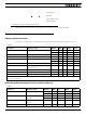
Electrical Specifications
Absolute Maximum Values
The values in the table below should never be exceeded, permanent damage to the controller may result.
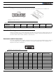
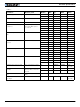
Power Stage Electrical Specifications (at 25oC ambient)
TABLE 6.
Parameter Measure point Model Min Typ Max Units
Battery Leads Voltage Ground to VBat XDC2x30 35 Volts
XDC2x60 62 Volts
Reverse Voltage on Battery Leads Ground to VBat All -1 Volts
Power Control Voltage Ground to Pwr Control wire All 35 Volts
Motor Leads Voltage Ground to M1+, M1-, M2+, M2- XDC2x30 35(1) Volts
XDC2x60 62 (1) Volts
Digital Output Voltage Ground to Output pins All 30 Volts
Analog and Digital Inputs Voltage Ground to any signal pin on 25 & 9-
pin connectors
All 15 Volts
RS232 I/O pins Voltage External voltage applied to Rx/Tx pins All 15 Volts
Case Temperature Case All -40 85 oC
Humidity Case All 100 (2) %
Note 1: Maximum regeneration voltage in normal operation. Never inject a DC voltage from a battery or other fixed source
Note 2: Non-condensing
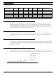
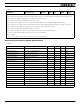
TABLE 7.
Parameter Measure point Models Min Typ Max Units
Battery Leads Voltage Ground to VBat XDC2x30 0 (1) 35 Volts
XDC2x60 62
Motor Leads Voltage Ground to M1+, M1-,
M2+, M2-
XDC2x30 0 (1) 30 (2) Volts
XDC2x60 62 (2)
Power Control Voltage Ground to Power Control
wire
All 0 (1) 62 Volts
Minimum Operating Voltage VBat or Pwr Ctrl wires All 9 (3) Volts
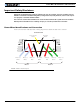
Under or Over Voltage
Power Stage Off
Short Detected
Overheat
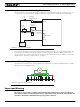
FIGURE 8. Exception or Fault Flashing Patterns