
Data Sheet

6 XDC2xxx Motor Controller Datasheet Version 1.3. November 6, 2014
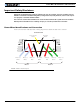
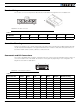
Encoder Wiring
The encoder connector is a 6-pin Molex Microfit 3.0, model 43645. Pin assignment is in the table below.
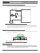
Controller Mounting
During motor operation, the controller will generate heat that must be evacuated. The published amps rating can
only be fully achieved if adequate cooling is provided. Mount the controller so that the bottom plate makes con-
tact with a metallic surface (chassis, cabinet) to conduct the heat.
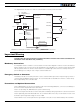
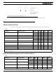
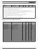
Commands and I/O Connections
Connection to RC Radio, Microcomputer, Joystick and other low current sensors and actuators is done via the 15
connector located in front of the board. The functions of many pins vary depending on user configuration. Pin
assignment is found in the table below.
TABLE 4.
Pin Number123456
Signal 5Vout Enc1A Enc1B Enc2A Enc2B GND
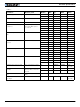
TABLE 5.
Connector Pin Power Dout Com RC Ana Dinput Default Config
1 DOUT1 Motor Brake
9 DOUT2 Safety Contactor
2 TxOut RS232Tx
10 ANA5 DIN5 AnaCmd1 (1)
3RxInRS232Rx
11 RC4 ANA4 DIN4 AnaCmd2 (1)
4 RC1 ANA1 DIN1 RCRadio1
12 RC3 ANA3 DIN3 Unused
5 GND
13 GND
61
6
1
FIGURE 5. Encoder connector
18
915
FIGURE 6. Connector pin locations