
Data Sheet

XDC2xxx Motor Controller Datasheet 5
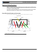
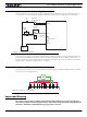
Use of Safety Contactor for Critical Applications
Use of Safety Contactor for Critical Applications
An external safety contactor must be used in any application where damage to property or injury to person can
occur because of uncontrolled motor operation resulting from failure in the controller’s power output stage.
The contactor coil must be connected to a digital output configured to activate when “No MOSFET Failure”. The
controller will automatically deactivate the coil if the output is expected to be off and battery current of 1A or
more is measured for more than 0.5s. This circuit will not protect against other sources of failure such as those
described in the “Important Safety Disclaimer” on page 3.
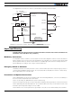
Single Channel Motor Wiring
The single channel version of the controller (XDC2xxxS) requires that the output be parallel and that the load be
wired as shown in the diagram below.
Important Warning
This wiring is only possible on controllers fitted with the Single Channel version of the controller logic.
Dual channel controllers will be damaged if wired as single channel. Verify that the PC utility identifies the
controller as XDC2230S or XDC2460S before applying power to the load.
PwrCtrl
SW1 Main
On/Off Switch 1A
F2
1A
Diode
>20A
Resistor
1K, 0.5W
+-
F1
I/O Connector
VMot
to +40V Max
Digital Out
Ground
Ground
Main
Battery
FIGURE 3. Contactor wiring diagram
M
M1+ GNDVMOT VMOTM1- M2+M2-
FIGURE 4. XDC2xxxS wiring diagram