
Data Sheet

4 XDC2xxx Motor Controller Datasheet Version 1.3. November 6, 2014
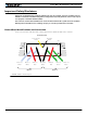
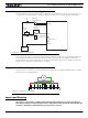
The diagram below shows how to wire the controller and how to turn power On and Off.
Important Warning
Carefully follow the wiring instructions provided in the Power Connection section of the User Manual. The
information on this datasheet is only a summary.
Mandatory Connections
It is imperative that the controller is connected as shown in the above diagram in order to ensure a safe and trou-
ble-free operation. All connections shown as thick black lines are mandatory. The controller must be powered On/
Off using switch SW1on the Power Control Header. Use a suitable high-current fuse F1 as a safety measure to
prevent damage to the wiring in case of major controller malfunction.
Emergency Switch or Contactor
The battery must be connected in permanence to the controller’s VMot power via an input emergency switch or
contactor SW2 as additional safety measure. The user must be able to deactivate the switch or contactor at any
time, independently of the controller state.
Precautions and Optional Connections
Note 1: Backup battery to ensure motor operation with weak or discharged batteries, connect a second battery to
the Power Control wire/terminal via the SW1 switch.
Note 2: Use precharge 1K, 0.5W Resistor to prevent switch arcing.
Note 3: Insert a high-current diode to ensure a return path to the battery during regeneration in case the fuse is blown.
Note 4: Optionally ground the VMot tabs when the controller is Off if there is any concern that the motors could
be made to spin and generate voltage in excess of 30V.
Note 5: Beware not to create a path from the ground pins on the I/O connector and the battery minus terminal.
Motor 1
VMot/Red
PwrCtrl/Yellow
SW1 Main
On/Off Switch 1A
F2
1A
Diode
>20A
Resistor
1K, 0.5W
+-
SW2
Emergency
Contactor or
Cut-off Switch
F1
White/M1+
Green/M1-
White/M2+
Green/M2-
Earth Tab
I/O Connector
VMot/Red
Ground/Black
Ground/Black
Ground/Black
Motor 2
Main
Battery
Backup
Battery
Note 5
Note 6
Do not Connect!
Note 1
Note 4
Note 3 Note 2
FIGURE 2. Powering the controller. Thick lines identify MANDATORY connections