
User Manual

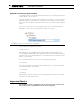
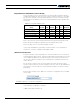
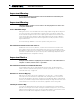
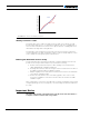
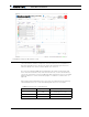
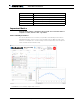
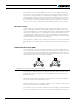
Table Of Contents
- Revision History
- Introduction
- Refer to the Datasheet for Hardware-Specific Issues
- User Manual Structure and Use
- SECTION 1 Connecting Power and Motors to the Controller
- SECTION 2 Safety Recommendations
- SECTION 3 Connecting Sensors and Actuators to Input/Outputs
- SECTION 4 I/O Configuration and Operation
- SECTION 5 Magnetic Sensor
- SECTION 6 Command Modes
- SECTION 7 Motor Operating Features and Options
- SECTION 8 Brushless Motor Connections and Operation
- SECTION 9 AC Induction MotorOperation
- SECTION 10 Closed Loop Speed and Speed Position Modes
- SECTION 11 Closed Loop Relative and Tracking Position Modes
- SECTION 12 Closed Loop Count Position Mode
- SECTION 13 Closed Loop Torque Mode
- SECTION 14 Serial (RS232/RS485/USB/TCP) Operation
- SECTION 15 Commands Reference
- SECTION 1: Connecting Power and Motors to the Controller
- Power Connections
- Controller Power
- Controller Powering Schemes
- Mandatory Connections
- Connection for Safe Operation with Discharged Batteries (note 1)
- Use precharge Resistor to prevent switch arcing (note 2)
- Protection against Damage due to Regeneration (notes 3)
- Connect Case to Earth if connecting AC equipment (note 4)
- Avoid Ground loops when connecting I/O devices (note 5)
- Connecting the Motors
- Single Channel Operation
- Power Fuses
- Wire Length Limits
- Electrical Noise Reduction Techniques
- Battery Current vs. Motor Current
- Measured and Calculated Currents
- Power Regeneration Considerations
- Using the Controller with a Power Supply
- SECTION 2: Safety Recommendations
- SECTION 3: Connecting Sensors and Actuators to Input/Outputs
- Controller Connections
- Controller’s Inputs and Outputs
- Connecting devices to Digital Outputs
- Connecting Switches or Devices to direct Digital Inputs
- Connecting a Voltage Source to Analog Inputs
- Connecting Tachometer to Analog Inputs
- Connecting External Thermistor to Analog Inputs
- Using the Analog Inputs to Monitor External Voltages
- Connecting Sensors to Pulse Inputs
- Connecting SSI Sensors
- Connecting Optical Encoders
- Connecting the Encoder
- SECTION 4: I/O Configuration and Operation
- Basic Operation
- Input Selection
- Digital Inputs Configurations and Uses
- Analog Inputs Configurations and Use
- Pulse Inputs Configurations and Uses
- Digital Outputs Configurations and Triggers
- Encoder Configurations and Use
- SSI Configuration and Use
- Hall and other Rotor Sensor Inputs
- Sensor Min Max values
- Relative Speed
- Brake Release
- Roboteq Products Connection and Operation
- SECTION 5: Roboteq Products Connection and Operation
- SECTION 6: Command Modes
- Input Command Modes and Priorities
- Operating the Controller in RC mode
- Using Sensors with PWM Outputs for Commands
- Operating the Controller In Analog Mode
- Monitoring and Telemetry in RC or Analog Modes
- Using the Controller with a Spektrum Satellite Receiver
- Using the Controller in Serial (USB/RS232/RS485/TCP) Mode
- SECTION 7: Motor Operating Features and Options
- SECTION 8: Brushless Motor Connections and Operation
- SECTION 9: AC Induction MotorOperation
- SECTION 10: Closed Loop Speed and Speed-Position Modes
- SECTION 11: Closed Loop Relative and Tracking Position Modes
- Modes Description
- Selecting the Position Modes
- Position Feedback Sensor Selection
- Sensor Mounting
- Feedback Sensor Range Setting
- Adding Safety Limit Switches
- Using Current Trigger as Protection
- Operating in Closed Loop Relative Position Mode
- Operating in Closed Loop Tracking Mode
- Position Mode Relative Control Loop Description
- PID tuning in Position Mode
- PID Tuning Differences between Position Relative and Position Tracking
- Loop Error Detection and Protection
- SECTION 12: Closed Loop Count Position Mode
- SECTION 13: Closed Loop Torque Mode
- SECTION 14: Serial (RS232/ RS485/USB/TCP) Operation
- SECTION 15: Commands Reference
- Commands Types
- Runtime Commands
- AC Set Acceleration
- AX Next Acceleration
- B Set User Boolean Variable
- BND Spectrum Bind
- C Set Encoder Counters
- CB Set Brushless Counter
- CG Set Motor Command via CAN
- CS CAN Send
- CSS Set SSI Sensor Counter
- CU Raw Redirect Send
- D0 Reset Individual Digital Out bits
- D1 Set Individual Digital Out bits
- DC Set Deceleration
- DS Set all Digital Out bits
- DX Next Deceleration
- EES Save Configuration in EEPROM
- EX Emergency Stop
- G Go to Speed or to Relative Position
- GIQ Go to Torque Amps
- GID Go to Torque Amps
- H Load Home counter
- MG Emergency Stop Release
- MS Stop in all modes
- P Go to Absolute Desired Position
- PR Go to Relative Desired Position
- PRX Next Go to Relative Desired Position
- PX Next Go to Absolute Desired Position
- R MicroBasic Run
- RC Set Pulse Out
- S Set Motor Speed
- SFT Safety Stop
- STT STO Self-Test
- SX Next Velocity
- VAR Set User Variable
- DS402 Runtime Commands
- CW – Control Word (DS402)
- Profile Position Mode
- Velocity Mode
- Other Modes
- FEW Following Error Window (DS402)
- FET Following Error Time Out (DS402)
- INT Interpolation Time Period (DS402)
- MSL Target Profile Velocity (DS402)
- PAC – Profile Acceleration (DS402)
- PDC – Profile Deceleration (DS402)
- PLT Software Position Limit (DS402)
- POS – Target Position (DS402)
- PSP – Profile Velocity (DS402)
- ROM – Modes of Operation (DS402)
- S16 – Target Velocity (DS402)
- SAC – Velocity Acceleration (DS402)
- SDC – Velocity Deceleration (DS402)
- SPC Target Profile Velocity (DS402)
- SPL – Velocity Min/Max Amount (DS402)
- TC – Target Torque (DS402)
- TSL – Torque Slope (DS402)
- Runtime Queries
- A Read Motor Amps
- AI Read Analog Inputs
- AIC Read Analog Input after Conversion
- ANG Read Rotor Angle
- ASI Read Raw Sin/Cos sensor
- B Read User Boolean Variable
- BA Read Battery Amps
- BCR Read Brushless Count Relative
- BMC Read BMS State Of Charge in AmpHours
- BMF Read BMS status flags
- BMS Read BMS switch states
- BS Read BL Motor Speed in RPM
- BSC Read BMS State of Charge in percentage
- BSR Read BL Motor Speed as 1/1000 of Max RPM
- C Read Encoder Counter Absolute
- CAN Read Raw CAN frame
- CB Read Absolute Brushless Counter
- CD Read Raw Redirect Received Frames Count
- CF Read Raw CAN Received Frames Count
- CHS CAN Consumer Heartbeat Status
- CIA Read Converted Analog Command
- CIP Read Internal Pulse Command
- CIS Read Internal Serial Command
- CL Read RoboCAN Alive Nodes Map
- CR Read Encoder Count Relative
- CSR Read Relative SSI Sensor Counter
- CSS Read Absolute SSI Sensor Counter
- D Read Digital Inputs
- DDT Read Raw Redirect Received Frame
- DI Read Individual Digital Inputs
- DO Read Digital Output Status
- DPA Read DC/Peak Amps
- DR Read Destination Reached
- E Read Closed Loop Error
- F Read Feedback
- FC Read FOC Angle Adjust
- FLW Read Flow Sensor Counter
- FF Read Fault Flags
- FID Read Firmware ID
- FIN Read Firmware ID (numerical)
- FM Read Runtime Status Flag
- FS Read Status Flags
- HS Read Hall Sensor States
- ICL Is RoboCAN Node Alive
- K Read Spektrum Receiver
- LK Read Lock status
- M Read Motor Command Applied
- MA Read Field Oriented Control Motor Amps
- MGD Read Magsensor Track Detect
- MGM Read Magsensor Markers
- MGS Read Magsensor Status
- MGT Read Magsensor Track Position
- MGY Read Magsensor Gyroscope
- MGX Read MagSensor Tape Cross Detection
- P Read Motor Power Output Applied
- PHA Read Phase Amps
- PI Read Pulse Inputs
- PIC Read Pulse Input after Conversion
- S Read Encoder Motor Speed in RPM
- SCC Read Script Checksum
- SDT Read Raw Redirect Received Frame as string
- SEC Read Sensor Errors
- SNA Read Sensor Angle
- SR Read Encoder Speed Relative
- SS Read SSI Sensor Motor Speed in RPM
- SSR Read SSI Sensor Speed Relative
- STT STO Self-Test Result
- T Read Temperature
- TM Read Time
- TR Read Position Relative Tracking
- TRN Read Control Unit type and Controller Model
- UID Read MCU Id
- V Read Volts
- VAR Read User Integer Variable
- SL Read Slip Frequency
- DS402 Runtime Queries
- AOM – Modes of Operation Display (DS402)
- CW – Control Word (DS402)
- SPE – Velocity Actual Value (DS402)
- FEW Following Error Window (DS402)
- FET Following Error Time Out (DS402)
- INT Interpolation Time Period (DS402)
- MSL Max Motor Speed (DS402)
- PAC – Profile Acceleration (DS402)
- PDC – Profile Deceleration (DS402)
- PLT Software Position Limit (DS402)
- PST Position Actual Value
- POS – Target Position (DS402)
- PSP – Profile Velocity (DS402)
- RMP – VL Velocity Demand (DS402)
- ROM – Modes of Operation (DS402)
- S16 – Target Velocity (DS402)
- SAC – Velocity Acceleration (DS402)
- SDC – Velocity Deceleration (DS402)
- SDM – Supported Drive Modes (DS402)
- SPL – Velocity Min/Max Amount (DS402)
- SW – Status Word (DS402)
- TC – Target Torque (DS402)
- TRQ – Target Torque (DS402)
- TSL – Profile Acceleration (DS402)
- VNM – Version Number (DS402)
- Query History Commands
- Maintenance Commands
- CLMOD – Motor/Sensor Setup
- CLRST Reset configuration to factory defaults
- CLSAV Save calibrations to Flash
- DFU Update Firmware via USB
- EELD Load Parameters from EEPROM
- EELOG Dump Flash Log Data
- EERST Reset Factory Defaults
- EESAV Save Configuration in EEPROM
- ERASE Erase Flash Log Data
- LK Lock Configuration Access
- RESET Reset Controller
- SLD Script Load
- STIME Set Time
- UK Unlock Configuration Access
- Set/Read Configuration Commands
- General Configuration and Safety
- ACS Analog Center Command to Start
- AMS Analog keep within Guard Bands
- BEE User Storage in Battery Backed RAM
- BRUN Script Auto-Start
- CLIN Command Linearity
- CPRI Command Priorities
- DFC Default Command value
- DMOD – Modbus Mode
- ECHOF Enable/Disable Serial Echo
- EE User-Defined Values
- ISM Raw Redirect Mode
- MDAL – Modbus Data Alignment
- MNOD – Modbus Slave ID
- PMS Pulse keep within Min & Max Safety
- RSBR Set RS232/RS485 baudrate
- RS485 Enable RS485
- RWD Serial Data Watchdog
- SCRO Select Print output port for scripting
- SKCTR Spektrum Center
- SKDB Spektrum Deadband
- SKLIN Spektrum Linearity
- SKMAX Spektrum Max
- SKMIN Spektrum Min
- SKUSE Assign Spektrum port to motor command
- STO – STO Enable
- TELS Telemetry String
- Analog, Digital, Pulse IO Configurations
- ACTR Analog Input Center (0)
- ADB Analog Input Deadband
- AINA Analog Input Use
- ALIN Analog Input Linearity
- AMAX Analog Input Max
- AMAXA Analog Input Action at Max
- AMIN Analog Input Min
- AMINA Analog Input Action at Min
- AMOD Analog Conversion Type
- APOL Analog Input Conversion Polarity
- DINA Digital Input Action
- DINL Digital Input Active Level
- DOA Digital Output Action
- DOL Digital Outputs Active Level
- PCTR Pulse Input Center
- PDB Pulse Input Deadband
- PINA Pulse Input Use
- PLIN Pulse Input Linearity
- PMAX Pulse Input Max
- PMAXA Pulse Input Action at Max
- PMIN Pulse Input Min
- PMINA Pulse Input Action at Min
- PMOD Pulse Input Capture Type
- PPOL Pulse Input Capture Polarity
- Motor Configurations
- ALIM Amps Limit
- ATGA Amps Trigger Action
- ATGD Amps Trigger Delay
- ATRIG Amps Trigger Level
- BKD Brake Delay
- BPR Bypass Trajectory/Ramp
- BRV Brake Release Voltage
- BHV Brake Hold Voltage
- BDT Brake Delay Time
- BLFB Closed loop Feedback Sensor
- BLSTD Stall Detection
- CLERD Close Loop Error Detection
- EDEC Motor Fault Deceleration Rate
- EHL Encoder Max Limit
- EHLA Encoder Action at Max
- EHOME Encoder Home Count
- ELL Encoder Min Limit
- ELLA Encoder Action at Min
- EMOD Encoder Usage
- EPPR Encoder Pulse/Rev Value
- ICAP PID Integrator Limit
- KDG PID Differential Gain
- KIG PID Integral Gain
- KPG PID Proportional Gain
- MAC Motor Acceleration Rate
- MDEC Motor Deceleration Rate
- MLX Molex Input
- MDIR Motor Direction
- MMOD Operating Mode
- MNRPM Min Speed RPM
- MVEL Position Mode Velocity
- MXMD Mixed Mode
- MXPF Motor Max Power Forward
- MXPR Motor Max Power Reverse
- MXRPM Max Speed RPM
- MXTRN Position Turns Min to Max
- OVH Overvoltage hysteresis
- OVL Overvoltage Limit
- OTL Over Temperature Limit
- SED Sensor Error Detection
- SCPR SSI Sensor Resolution
- SHL SSI Sensor Max Limit
- SHLA SSI Sensor Action at Max
- SHOME SSI Sensor Home Count
- SLL SSI Sensor Min Limit
- SLLA SSI Sensor Action at Min
- SMOD SSI Sensor Usage
- TNM Motor Torque Constant
- UVL Undervoltage Limit
- Brushless Specific Commands
- BADJ Brushless Angle Zero Adjust
- BADV Brushless timing angle adjust
- BECC – BEMF Coupling Constant
- BFBK Brushless Sinusoidal Angle Sensor
- BHL Brushless Internal Sensor Max Limit
- BHLA Brushless Internal Sensor Action at Max
- BHOME Brushless Internal Sensor Home Count
- BLL Brushless Internal Sensor Min Limit
- BLLA Brushless Internal Sensor Action at Min
- BMOD Brushless Switching Mode
- BPOL Number of Pole Pairs
- BZPW Brushless Reference Seek Power
- HPO Hall Sensor Position Type
- HSAT Hall Sensor Angle Table
- HSM Hall Sensor Map
- KIF Current PID Integral Gain
- KPF Current PID Proportional Gain
- LD Motor d-axis Inductance
- LQ Motor q-axis Inductance
- PSA Phase Shift Angle
- RS Motor Stator Resistance
- SPOL SinCos/SSI Sensor Poles
- SSF – Sensorless Start-Up Frequency
- SVT – BEMF Integrator Limit
- SWD Swap Windings
- TID FOC Target Id
- VK Motor Voltage constant
- ZSMA Cos Amplitude
- ZSMC SinCos Calibration
- AC Induction Specific Commands
- BFBK AC Induction Operating Mode
- ILM Mutual Inductance
- ILLR Rotor Leakage Inductance
- IRR Rotor Resistance
- MPW Minimum Power
- MXS Optimal Slip Frequency
- RFC Rotor Flux Current
- VPH AC Induction Volts per Hertz
- CAN Communication Commands
- CAS CANOpen Auto start
- CBR CAN Bit Rate
- CEN CAN Mode
- CHB CAN Heartbeat
- CHLA CAN Consumer Heartbeat Lost Action
- CLSN CAN Listen Node ID
- CNOD CAN Node ID
- CSRT MiniCAN SendRate
- CTPS CANOpen TPDO SendRate
- CTT – CANOpen Transmission Type
- FSA – DS402 PDS Finite State Automation Enable
- DHCP Enable DHCP
- GWA Gateway Address
- IPA IP Address
- IPP IP Port
- PDNS Primary DNS
- SBM Subnet Mask
- SDNS Primary DNS
- WMOD TCP Mode

Sinusoidal Commutation
Advanced Digital Motor Controller User Manual 115
Important Warning
Do not select an amperage value that is above the maximum nominal value pub-
lished in the motor’s datasheet.
Important Warning
Calibration data is specific to a motor+sensor set. Changing the motor and/or sen-
sor requires recalibration.
Sensor Min/Max Range
Analog sensors like Sin/Cos and Resolvers have voltage output swings that can vary from
one sensor to another. During Automatic Setup, the motor is forced into rotation and
the min and max voltages for each sensor output signal is captured over a full turn of the
sensor. These values then determine offsets and multiplier that are saved in calibration
memory and subsequently used to scale the signals as necessary to produce a correct
angle measurement.
The min/max range calibration is a one time operation for a given sensor.
Zero Reference Search for Absolute Sensors
All absolute sensors (Sin/Cos, Resolver, SSI) cannot be trusted to be mounted so that
their 0 degree reference position exactly matches this of the motor’s windings. During
Zero Reference search, the motor is driven over known angular positions. The sensor mea-
surement is compared with the expected rotor position and an Angle Adjustment vale is
computed and stored in configuration memory.
Important Notice
All angles values entered or displayed by the controller are in 0-511 value where 0 =
0 degrees or radians, and 511 is 360o or 2r radians.
Zero Reference Search for Incremental Encoders
Incremental Encoders do not output an absolute position value. The Zero Reference
search is therefore performed every time the controller is powered on. See also “Incre-
mental Encoder-Only” on page 103
Hall Sensors Position Mapping
Hall sensors are often not precisely located at the 0, 60, 120, 180, ... positions. While
some imprecision has little effect in trapezoidal mode, misalignment of even a few de-
grees will have disruptive effect when operating in sinusoidal mode. When used with Hall
sensors, the automatic setup procedure captures and maps the angle at which each of the
six hall transitions occurs within an electrical turn, regardless of their wiring order.
Linearity Correction Map
Sensor are not alway totally linear. This causes the sensed angle to be measured with
periodic errors along the sensor travel. During the automatic setup process, the controller
maps the values read from the sensor for every mechanical degree over a full turn. It then
build a correction table which is applied in real-time as the motor spins.