
Data Sheet

9 SBL23xx Motor Controller Datasheet Version 1.2 March 27, 2018
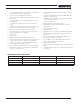
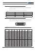
Commands and I/O Connections
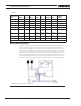
TABLE 4.
Connector
Pin Power Dout Com Pulse Ana Dinput Enc
Default
Config
9 ASIN1 DIN9 Unused
22 RC6 ANA6 DIN6 ENC2B Unused
10 ACOS1 DIN10 Unused
23 RS485+ RS485+
11 RS485- RS485-
24 RC7 ANA7/
ASIN2
DIN7 ENC1A Unused
12 RC8 ANA8/
ACOS2
DIN8 ENC1B Unused
25 5VOut
13 GND
Note 1: Analog command is disabled in factory default configuration.
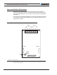
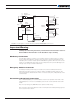
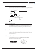
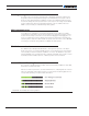
Default I/O Configuration
While the controller can be configured so that practically any Digital, Analog and RC pin
can be used for any pur pose, the controller’s factory default configuration provides an
assignment that is suitable for most applications. Figure 9, below, shows how to wire the
controller to two analog potentiometers, an RC radio, and the RS232 port. It also shows
how to connect two outputs to motor brake solenoids and another output to an external
status LED. You may omit any connection that is not required in your application. The con-
troller automatically arbitrates the command priorities depending on the presence of a
valid command signal in the following order: 1-RS232, 2-RC Pulse, 3-None. If needed, use
the Roborun+ PC Utility to change the pin assignments and the command prior ity order.
FIGURE 9. Factory Default Pin Assignment