
Data Sheet

8 SBL23xx Motor Controller Datasheet Version 1.2 March 27, 2018
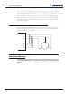
Connection to Analog Sin/Cos Absolute Encoder
The SBL23xx has four high-speed analog inputs that can be used to capture absolute an-
gle position from angular sensors with sin/cos voltage outputs. The signal must be 0-5V
max with the 0 at 2.500V.
Table 3, below, shows the signals assignment on the 25-pin connector.
TABLE 3.
Signal Pin Number Pin Name
Sin1 9 ASIN1
Cos1 10 ACOS1
Sin2 24 ANA7/ASIN2
Cos2 12 ANA8/ACOS2
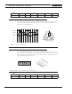
Commands and I/O Connections
Connection to RC Radios, Microcomputers, Joysticks and other low current sensors and
actuators are done via the 25-pin connector. The functions of many pins vary depending on
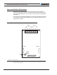
controller model and user configuration. Pin assignments can be found in Table 4, below.
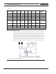
113
14 25
FIGURE 8. Main Connector Pin Locations
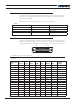
TABLE 4.
Connector
Pin Power Dout Com Pulse Ana Dinput Enc
Default
Config
1 GND
14 5VOut
2 RS TxD RS232Tx
15 RC1 ANA1 DIN1 RCRadio1
3 RS RxD RS232Rx
16 RC2 ANA2 DIN2 RCRadio2
4 RC3 ANA3 DIN3 AnaCmd1 (1)
17 RC4 ANA4 DIN4 AnaCmd2 (1)
5 GND
18 DOUT1 Motor Brake 1
6 DOUT2 Motor Brake 2
19 DOUT3 Contactor
7 DOUT4 Unused
20 CANH
8 CANL
21 RC5 ANA5 DIN5 ENC2A Unused