
Data Sheet

6 SBL23xx Motor Controller Datasheet Version 1.2 March 27, 2018
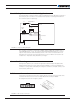
Use of Safety Contactor for Critical Applications
An external safety contactor must be used in any application where damage to property or
personal injury can occur due to uncontrolled motor operation resulting from a failure in
the controller’s power output stage.
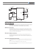
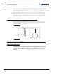
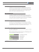
FIGURE 4. Contactor Wiring Diagram
The contactor coil must be connected to a digital output configured to activate when a
“No MOSFET Failure” occurs. The controller will automatically deactivate the coil if the
output is expected to be off and a battery current of 1A or more is measured for more
than 0.5s. This circuit will not protect against other sources of failure such as those de-
scribed in the “Important Safety Disclaimer”, on Page3.
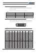
Controller Mounting
During motor operation, the controller will generate heat that must be dissipated. The
published amps rating can only be fully achieved if adequate cooling is provided. Good
conduction cooling can be achieved by mounting the controller to a metallic surface, such
as the chassis, cabinet, etc.
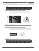
Hall Sensors Connection
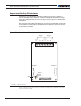
Connection to the Hall Sensors is done using a special connector on the front side of the
controller. The Hall sen sor connector is a 6-pin Molex Microfit 3.0, ref. 43645.
Pin assignment are shown in Figure 5, below:
61
6
1
FIGURE 5. Hall Sensors Connector
PwrCtrl
SW1 Main
On/Off Switch 1A
F2
1A
Diode
>20A
Resistor
1K, 0.5W
+-
F1
I/O Connector
VMot
to +40V Max
Digital Out
Ground
Ground
Main
Battery
FIGURE 1.Contactor wiring diagram