
Data Sheet

5 SBL23xx Motor Controller Datasheet Version 1.2 March 27, 2018
Single Channel Wiring
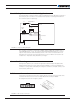
Note 4: Users have the option to ground the VMot terminal when the controller is Off.It is
recommended that users do this if there is any concern that the motors could be made to
spin and generate voltage in excess of 30V on the SBL2330 or 60V on the SBL2360.
Note 5: Connect the controller’s bottom plate to a wire connected to the Earth while the
charger is plugged in the AC main, or if the controller is powered by an AC power supply.
Note 6: Be careful not to create a path from the ground pins on the I/O connector and the
battery minus terminal.
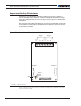
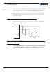
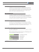
Single Channel Wiring
On the Single Channel SBL23xxS, each of the motor wires must be connected to both
output terminals of the same letter as shown in Figure 3, below. Use the Encoders and/or
Hall sensors of Channel 1 for operation.
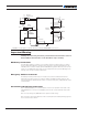
FIGURE 3. Single Channel Wiring Diagram
Important Warning
The wiring shown in Figure 3 must be done only on the single channel version of the
controller. Paralleling the wires on a dual channel product will cause permanent dam-
age. Verify that your controller is an SBL2330S or SBL2360S before you wire in this
manner.
U1
V1
W1
U2
V2
W2
U
V
W