
Data Sheet

4 SBL23xx Motor Controller Datasheet Version 1.2 March 27, 2018
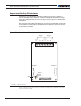
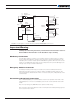
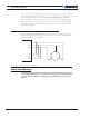
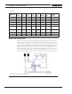
FIGURE 2. Powering the Controller. Thick lines identify MANDATORY connections
Important Warning
Carefully follow the wiring instructions provided in the Power Connection section of
the User Manual. The information on this datasheet is only a summary.
Mandatory Connections
It is imperative that the controller is connected as shown in Figure 2, above, in order to
ensure a safe and trou ble-free operation. All connections shown as thick black lines are
mandatory. The controller must be powered On/Off using switch SW1on the Pwr Ctrl ter-
minal. Use a suitable high-current fuse F1 as a safety measure to prevent damage to the
wiring in case of major controller malfunction.
Emergency Switch or Contactor
The battery must be permanently connected to the controller’s VMot terminal via a
high-power emergency switch or contactor SW2 as an additional safety measure. The
user must be able to deactivate the switch or contactor at any time, independently of the
controller state.
Precautions and Optional Connections
Note 1: A backup battery is recommended to ensure motor operation with weak or dis-
charged batteries. Connect a second battery to the Power Control terminal via the SW1
switch.
Note 2: Use precharge 1K, 0.5W Resistor to prevent switch arcing.
Note 3: Insert a high-current diode to ensure a return path to the battery during regenera-
tion in case the fuse is blown.
Controller Power
Motor Wires
VMot GroundGround
(top)
Power Control
VMot
PwrCtrl
SW1 Main
On/Off Sw itch 1A
F2
1A
Diode
>20A
Resi stor
1K, 0.5W
+-
SW2
Emergency
Contactor or
Cut-off Switch
F1
Hall sensor
Connector
I/O Connector
Ground
Ground
Main
Battery
Backup
Battery
Note 6
Do not Connect!
Note 1
2 etoN 3 etoN
U1 U2 V1 V2 W1 W2
Note 5
Note 4
Motor1
Hall
Sensors1
U1
V1 W1
Motor2
Hall
Sensors2
U2
V2 W2
U1
V1
W1
U2
V2
W2