
Data Sheet

13 SBL23xx Motor Controller Datasheet Version 1.2 March 27, 2018
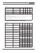
Electrical Specifications
TABLE 6.
Parameter Measure point Model Min Typ Max Units
Stall Detection Amps range Motor current SBL23xx 10 30 (7) 30 Amps
SBL23xxS 20 60 (7) 60 Amps
Stall Detection timeout
range
Motor current All 1 500 (8) 65000 milli-
seconds
Short Circuit Detection
threshold (9)
Between Motor
wires or Between
Motor wires and
round
SBL23xx 85 (10) Amps
SBL23xxS 190
(10)
Amps
Short Circuit Detection
threshold
Between Motor
wires and VBat
All
No Protection.
Permanent damage will result
Motor Acceleration/
Deceleration range
Motor Output
All
100 500
(11)
65000
milli-
seconds
Note 1: Negative voltage will cause a large surge current. Protection fuse needed if battery polarity inver-
sion is possible
Note 2: Maximum regeneration voltage in normal operation. Never inject a DC voltage from a battery or
other fixed source
Note 3: Minimum voltage must be present on VMot or Power Control wire
Note 4: Factory default value. Adjustable in 0.1V increments
Note 5: Current consumption is lower when higher voltage is applied to the controller’s VMot or PwrCtrl
Note 6: Estimate. Limited by case temperature. Current may be higher with better cooling
Note 7: Factory default value. Adjustable in 0.1A increments
Note 8: Factory default value. Time in ms that Stall current must be exceeded for detection
Note 9: Controller will stop until restarted in case of short circuit detection
Note 10: Approximate value
Note 11: Factory default value. Time in ms for power to go from 0 to 100%
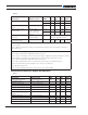
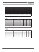
Command, I/O and Sensor Signals Specifications
TABLE 7.
Parameter Measure point Min Typ Max Units
Main 5V Output Voltage Ground to 5V pins on 4.6 4.75 4.9 Volts
5V Output Current 5V pins on Molex and DSub25 100 (1) mA
Digital Output Voltage Ground to Output pins 30 (2) Volts
Output On resistance Output pin to ground 0.25 0.5 Ohm
Output Short circuit threshold Output pin 1. 7 3.5 Amps
Digital Output Current Output pins, sink current 1.5 (2) Amps
Input Impedances (except
DIN7-8)
AIN/DIN Input to Ground 53 kOhm
Digital Input 0 Level Ground to Input pins -1 1 Volts
Digital Input 1 Level Ground to Input pins 3 30 Volts
Analog Input Range Ground to Input pins 0 5.1 Volts
Analog Input Precision Ground to Input pins 0.5 %