
Data Sheet
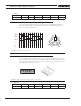

12 SBL23xx Motor Controller Datasheet Version 1.2 March 27, 2018
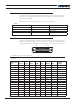
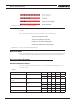
TABLE 5.
Parameter Measure point Model Min Typ Max Units
Analog and Digital Inputs
Voltage
Ground to any signal pin
on 15-pin & Hall inputs
All 30 Volts
RS232 I/O pins Voltage External voltage applied
to Rx pin
All 30 (3) Volts
Case Temperature Case All -40 85 ºC
Humidity Case All 100 (4) %
Note 1: Maximum regeneration voltage in normal operation. Never inject a DC voltage from a battery or
other fixed source
Note 2: Outputs are Open Drain. They pull to ground when on and float when off. Load must be connect-
ed between output and positive voltage
Note 3: No external voltage must be applied to Rx pin. Damage to driver will occur
Note 4: Non condensing
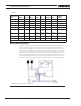
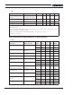
Power Stage Electrical Specifications (at 25oC ambient)
TABLE 6.
Parameter Measure point Model Min Typ Max Units
Battery Leads Voltage Ground to VMot SBL2360 0 (1) 63 Volts
SBL2330 0 (1) 35 Volts
Motor Leads Voltage Ground to U, V, W
wires
SBL2360 0 (1) 63 (2) Volts
SBL2330 0 (1) 35 (2) Volts
Power Control Voltage Ground to Power
Control wire
All 0 (1) 30 Volts
Minimum Operating Voltage VBat or Pwr Ctrl wires All 9 (3) Volts
Over Voltage protection
range
Ground to VMot SBL2360 5 60 (4) 63 Volts
SBL2330 5 30 (4) 35 Volts
Under Voltage protection range Ground to VMot SBL2360 0 5 (4) 63 Volts
SBL2330 0 5 (4) 35 Volts
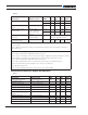
Idle Current Consumption VMot or Pwr Ctrl
wires
All 50 100 (5) 150 mA
ON Resistance (Excluding
wire resistance)
VMot to U, V or W.
Ground to U, V or W
SBL23xx 9.0 mOhm
SBL23xxS 4.5 mOhm
Max Current for 30s Motor current SBL23xx 30 Amps
SBL23xxS 60 Amps
Continuous Max Current per
channel
Motor current SBL23xx 20 (6) Amps
SBL23xxS 40 Amps
Current Limit range Motor current SBL23xx 10 50 (7) 30 Amps
SBL23xxS 20 100 (7) 60 Amps