
Data Sheet

11 SBL23xx Motor Controller Datasheet Version 1.2 March 27, 2018
Electrical Specifications
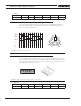
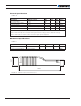
FIGURE 11. Exception or Fault Flashing Patterns
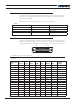
Additional status information may be obtained by monitoring the controller with the
PC utility.
The communication LED gives status information on the CAN and USB.
Always off: No USB, No CAN
Always On: USB Active, No CAN
Flashing On: No USB, CAN Enabled
Flashing Off: USB Active, CAN Enabled
FIGURE 12. Communication LED Flashing Patterns
Measured Amps
The controller includes Amps sensors in line with the motor terminals and on the battery ground
terminals. Both Motor Amps and Battery Amps are therefore measured with precision.
Electrical Specifications
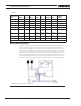
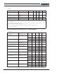
Absolute Maximum Values
The values in Table 5, below, should never be exceeded, permanent damage to the con-
troller may result.
TABLE 5.
Parameter Measure point Model Min Typ Max Units
Battery Leads Voltage Ground to VBat SBL2360 63 Volts
SBL2330 35 Volts
Reverse Voltage on Battery
Leads
Ground to VBat All -1 Volts
Power Control Voltage Ground to Pwr Control
wire
SBL2360 30 Volts
SBL2330 30 Volts
Motor Leads Voltage Ground to U, V, W wires SBL2360 63 (1) Volts
SBL2330 35 (1) Volts
Digital Output Voltage Ground to Output pins All 40 (2) Volts