
Data Sheet

10 SBL23xx Motor Controller Datasheet Version 1.2 March 27, 2018
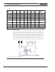
Enabling Analog Commands
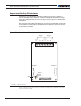
For safety reasons, the Analog command mode is disabled by default. To enable the An-
alog mode, use the PC utility and set Analog in Command Priority 2 or 3 (leave Serial as
priority 1). Note that by default, the additional securities are enabled and will prevent the
motor from starting unless the potentiometer is centered, or if the voltage is below 0.25V
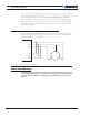
or above 4.75V. Figure 9 shows suggested assignment of Pot 1 to ANA1 and Pot 2 to
ANA4. Use the PC utility to enable and assign analog inputs.
USB communication
Use USB only for configuration, monitoring and troubleshooting. USB is not a reliable
communication method when used in an electrically noisy environment. Further, commu-
nication will not always recover after it is lost without unplugging and replugging the con-
nector, or restarting the controller. RS232 is the preferred communication method when
interfacing with a computer. USB and CAN can operate at the same time on the SBL2360.
Connecting to a computer using USB will not disable the CAN interface.
RS485 Communication
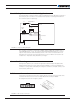
The SBL23xx has a half-duplex RS485 interface. Two signals are present on the 25-pin
DSub connector for connecting to RS485 networks. Connecting these two wires with the
correct polarity is all that is needed to establish a connection. The RS485+ is the positive
signal and RS485- is the inverted signal. Once enabled, the RS485 can be used to commu-
nicate data under the Modbus protocol, or Roboteq’s native serial commands.
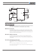
Status LEDs and Flashing Patterns
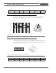
The controller is equipped with three LEDs. A Green Power LED, a Red/Green Status LED,
and a Yellow Communication LED.
After the controller is powered on, the Power LED will tun on, indicating that the controller
is On. The Status LED will be flashing at a two second interval. The flashing patterns and
colors provide operating or exception status infor mation.
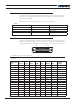
FIGURE 10. Normal Operation Flashing Patterns