
Data Sheet


8 SBL13xx Motor Controller Datasheet Version 1.1 March 29, 2018
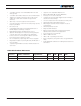
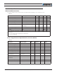
TABLE 3.
Connector Pin Power Dout Com RC Ana Dinput Enc Default Config
4 PIN1 ANA1 DIN1 ENCA (2) RCRadio1
12 PIN3 ANA3 DIN3 Unused
5 GND
13 GND
6 CANL CAN Low
14 5VOut
7 CANH CAN High
15 PIN6(5) ANA6/ACOS(1) DIN6
8 PIN2 ANA2 DIN2 ENCB (2) Unused
Note 1: ASIN, ACOS and EXC are only available on SBL13xxA
Note 2: Encoder input requires Pulse inputs 1 and 2 to be disabled. Pulse inputs are enabled in factory default.
Note 3: Analog command is disabled in factory default configuration.
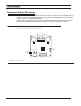
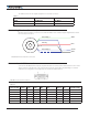
Default I/O Configuration
The controller can be configured so that practically any Digital, Analog and RC pin can be used for any purpose.
The controller’s factory default configuration provides an assignment that is suitable for most applications. The
figure below shows how to wire the controller to an analog potentiometer, an RC radio, the RS232 port, and the
Digital output to a motor brake solenoid. You may omit any connection that is not required in your application. The
controller automatically arbitrates the command priorities depending on the presence of a valid command signal
in the following order: 1-RS232, 2-RC Pulse, 3-None. If needed, use the Roborun+ PC Utility to change the pin
assignments and the command priority order.
18
915
1
Pot
RS232
Brake Release
Safety Contactor
Ground
TxOut
RxIn
RC Ch1
FIGURE 8. Factory Default Pin Assignment
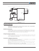
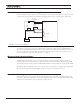
Enabling Analog Commands
For safety reasons, the Analog command mode is disabled by default. To enable the Analog mode, use the PC
utility and set Analog in Command Priority 2 or 3 (leave Serial as priority 1). Note that by default the additional
securities are enabled and will prevent the motor from starting unless the potentiometer is centered, or if the
voltage is below 0.25V or above 4.75V. The drawing shows suggested assignment of Pot 1 to ANA1. Use the
PC utility to enable and assign analog inputs.