
Data Sheet


SBL13xx Motor Controller Datasheet 7
Commands and I/O Connections
The table below shows the signals assignment on the 15-pin connector.
TABLE 2.
Signal Pin Number Pin Name
Sin 10 ANA5/ASIN
Cos 15 ANA6/ACOS
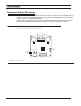
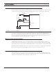
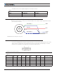
Connecting Resolver (A-version)
Resolver wiring is similar to a Sin/Cos sensor with the addition of an excitation signal. Diagram below shows
the necessary connections.
Primary
Secondary 1
ASIN
ACOS
EXC
GND
Secondary 2
FIGURE 6. A-Version Resolver Connection
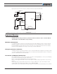
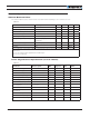
Commands and I/O Connections
Connection to RC Radio, Microcomputer, Joystick and other low current sensors and actuators is done via the
15-pin connector located in front of the controller. The functions of many pins vary depending on controller
model and user configuration. Pin assignments are found in the Table 3, below.
FIGURE 7. Connector Pin Locations
TABLE 3.
Connector Pin Power Dout Com RC Ana Dinput Enc Default Config
1 DOUT1 Brake
9 DOUT2
2 TxOut RS232Tx
10 PIN5(5) ANA5/ASIN(1) DIN5
3 RxIn RS232Rx
11 PIN4 ANA4/EXC(1) DIN4 AnaCmd (3)