
Data Sheet


SBL13xx Motor Controller Datasheet 5
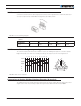
Controller Mounting
Use of Safety Contactor for Critical Applications
An external safety contactor must be used in any application where damage to property or injury to person can
occur because of uncontrolled motor operation resulting from failure in the controller’s power output stage.
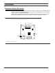
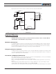
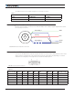
FIGURE 3. Contactor Wiring Diagram
The contactor coil must be connected to a digital output configured to activate when “No MOSFET Failure”.
The controller will automatically deactivate the coil if the output is expected to be off and battery current of 1A
or more is measured for more than 0.5s. This circuit will not protect against other sources of failure such as
those described in the “Important Safety Disclaimer” on Page3.
Measured and Calculated Amps
SBL13xx models include Amps sensor in line with the battery ground wires. Battery Amps are therefore
measured with precision. Motor Amps are estimated using the formula Motor Amps = Battery Amps / PWM.
This formula produces accurate results from 20% PWM and above. No Motor Amps are reported at 0% PWM.
SBL13xxA models include Amps sensors in line with the motor terminals and on the battery ground terminals.
On these models, both Motor Amps and Battery Amps are therefore measured with precision.
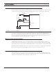
Controller Mounting
During motor operation, the controller will generate heat that must be evacuated. The published amps rating
can only be fully achieved if adequate cooling is provided. Mount the controller so that the bottom plate makes
con tact with a metallic surface (chassis, cabinet) to conduct the heat.
PwrCtrl
SW1 Main
On/Off Switch 1A
F2
1A
Diode
>20A
Resistor
1K, 0.5W
+-
F1
I/O Connector
VMot
to +40V Max
Digital Out
Ground
Ground
Main
Battery
FIGURE 1.Contactor wiring diagram