
Data Sheet


BMS10x0
6 www.roboteq.com Version 1.0 March 2, 2018
The CAN and RS485 pins can be connected to a twisted pair cable. The BMS can be
configured to operate in either of these communication modes.
Two Open Drain Digital Outputs are availalbe for connecting low-power accessories.
The BMS10x0 also implements a RoboteQ proprietary single wire PWM communication
protocol for exchanging the most vital battery information with RoboteQ’s motor
controllers. When using the PWM mode, external ground and 5V supply must be
connected to the GND and VCC pins. (See MultiPWM in BMS operation)
Push-Button and LEDs
One push button and three LED indicators are provided for quick diagnostics such as
charge level, communication, and other useful information. Different flashing patterns are
used to code the various information type.
USB Connector
A USB port is present for connecting the BMS to a PC running the dedicated PC Utilityfor
configuring the BMS’s various parameters (voltage, current, temperature thresholds, etc.),
monitoring real time operating values, capture/save logs and editing user scripts.
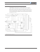
Pack+/Pack-Battery Connection
The Pack+ and Pack- are high-current screw terminals connected to the battery pack’s
mains; positive and negative. Current up to 100A can be transferred to the battery
during charge or regeneration and from the battery during discharge. A 16-pin connector
on the BMS10x0 is used for connecting each individual cell’s terminals for monitoring
and balancing.
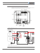
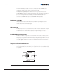
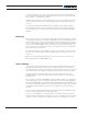
Temperature Thermistor Connector
The 6-pin connector provides the connections to up to three external 10K NTC thermistors
for monitoring temperature in the battery pack. Thermistors can be connected without at-
tention to polarity. Use Molex 2 rows x 3, 4.2mm pitch connector reference 0039012060,
or equivalent..
4
321
65
TC1
TC2TC3
BMS1040
BMS1060
FIGURE 5. Temperature Thermistor connections