
Data Sheet


BMS10x0
www.roboteq.com 5
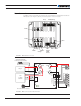
Load+/Load-Power Connectors to Load
Two high current screw terminals are used to connect to the user load. A 100A switch
built into the BMS will isolate these connections from the battery in case of over/under
voltage, short circuit, over current, over temperature or other unsafe conditions. Current is
allowed to flow back into the battery from regenerative loads if operating in the safe oper-
ation area.
Charge+/Charge-Connectors to Battery Charger
Two Faston connectors are used to connect the BMS to a charger. A 50A built-in switch
will disconnect the charger from the battery when it is fully charged or if any unsafe condi-
tion occurs.
Brake+/Brake-Connectors to External Resistor
These Faston connections can be used to connect a brake resistor to absorb regenera-
tive current from the main connectors when the batteries are already fully charged or an
unsafe condition has occurred. The brake resistor is externally connected by the user. Al-
ternatively, these connections can be used for attaching other high-current elements like a
battery heater or fans.
User I/O
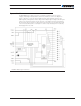
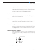
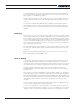
An 8-pin connector, as shown in Figure 4, contains the signal needed by the BMS to
communicate with other parts of the system.Use Molex 2 rows x 4-pin, 4.2mm pitch
connector reference 39-01-2080, or equivalent.
4321
8765
FIGURE 4. User IO Male Connector on BMS
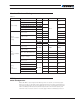
TABLE 1.
Pin Signal Description
1 CANH / RS485A High level CAN bus line / RS485 Direct (+)
2 CANL / RS485B Low level CAN bus line / RS485 Inverted (-)
3 DOUT1 1A Open Drain output 1
4 DOUT2 1A Open Drain output 2
5 VCC Optocoupler VCC in - 3.3 to 5 V typical operation
6 PWM Optocoupled PWM output
7 GND Optocoupler GND in
8 NC Reserved