
Data Sheet


BMS10x0
4 www.roboteq.com Version 1.0 March 2, 2018
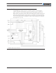
User Connections
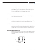
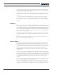
The BMS electronics board is mounted on top of an aluminum cooling plate and under an
ABS plastic cover. Figure 2, below, shows the position of its connectors.
Cell BalancingTemp
Pack
Load
Brake-Brake+
Charge+
CAN
RS485
PWM
DOUT
USB Button
Charge-
LEDs
FIGURE 2. BMS Board Connectors
LOAD
Charger
PACK
Brake+
Charge+
Temp
USB
CAN/RS485
(PWM)
Cell Balancing
Charge-
Brake-
++
--
- +
- +
- +
- +
- +
- +
- +
- +
Fan or other 1A max accessory
Battery
Pack
Optional Brake Resistor
or other high current accessory
Load
e.g. Motor
Controller
-
-
-
-
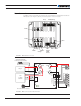
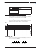
FIGURE 3. BMS Connections and Power Flow