
Data Sheet

BMS10x0
www.roboteq.com 17
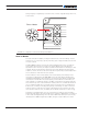
If an external power source is utilized, users must make sure that the external GND is
connected to the negative terminal of the pack.
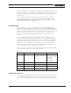
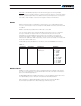
TABLE 7.
Command Arguments Description Examples
^DOA xx yy Output Index, Trigger Digital Output Active When ^DOA 1 0
xx 1: Dout1
2: Dout2
yy 0: Never
1: Over Temp
2: Over Volt
3: Overload/Short
^DOL xx yy Output Index, Level Digital Output Level Logic ^DOL 1 1
Scripting
Scripting is a common feature in every RoboteQ product and documentation can be found
on RoboteQ’s website (www.roboteq.com), including examples and tutorials.
With scripting all system variables can be accessed and manipulated. Custom strategies
can be implemented controlling the circuit breaker, digital outputs, auxiliary output,
dynamically adjusting protection thresholds etc.
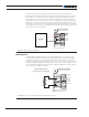
MultiPWM
As the name implies, this proprietary method uses a succession of variable duty-cycle
pulses to carry vital predefined information. Using MultiPWM the battery’s SoC, status
flags and system state can be obtained. All data is continuously transmitted to RoboteQ’s
motor controllers and the values may be requested any time by the commands BMC,
BMF and BMS.
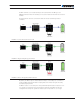
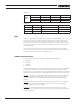
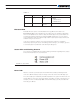
Status Flag bytes consist of [SCRIPT_RUN, BALANCING, BAD_SOH, INTERNAL_FAULT,
UV, OV, SC, OC]. The status represents user script running, that balancing is activated,
state of health error, internal fault, under voltage, over voltage, short circuit, over current,
respectively.
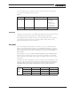
The 8 bits of the System State bytes are; cells are not properly connected, hard fault occurred,
system is in safe lock state, system regenerates energy, discharging enabled, balancing
enabled, charging enabled. These states are represented by the following, respectively:
NOCONNECT, FAIL, LOCK, RGN, DCH, BALANCE, CH. Refer to Tables 8-10, below:
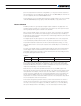
TABLE 8.
Status
Flags
Bit 7 Bit 6 Bit 5 Bit 4
SCRIPT_RUN BALANCING BAD_SOH INT_FAULT
Bit 3 Bit 2 Bit 1 Bit 0
UV OV SC OC