
Data Sheet

BMS10x0
www.roboteq.com 15
capacity. If the battery is then charged back to 100% and is discharged to 90%, we would
have a total of 20% the nominal capacity delivered. When this process is repeated 10
times, the total energy delivered would be equal to 100% the nominal capacity, thus one
full battery cycle.
Another example with different percentages is the following: A 100% SoC battery is
discharged to 70% (30% the nominal capacity delivered), then charged back to 90%
and discharged to 20% (70% delivered), which again gives a total of 100% the nominal
capacity delivered, meaning one full battery cycle.
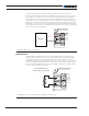
Circuit Breaker
The Circuit Breaker is one of the most important functions of the BMS10x0 and that is
because the first priority in any case is the protection of the battery and BMS board. The
Pack, Load, Charger and Brake Resistor can all be connected and isolated separately. The
circuit is fully operational by way of implementing internally all the necessary components.
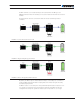
While the user may control the switches using the Microbasic script, the protection
actions are automatically triggered by default if any of the configured thresholds is
exceeded.
The board is designed to withstand up to 200 A peak current and 100 A continuous
current. The BMS10x0 is highly configurable and by configuring the battery’s parameters
the system can protect the cells from different over current conditions during charging or
discharging and different response times can be set for acting on a short circuit event.
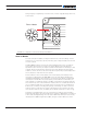
Response time is also configurable for over current protection. After an overload error
has been triggered the system will either lock or retry after the configured delay time to
connect to the channel for the configured number of retry times.
Protection measures are also taken when Over/Under Voltage or Over/Under Temperature
events occur, always with respect to the configured values.
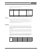
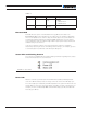
TABLE 5.
Command Arguments Description Examples
^THLD xx yy Channel, Value Set Response Time for
Short
^THLD 1 0
xx 1: Load, 2: Charge
yy 0: Quick
1: Medium
2: Slow
3: Disabled
^ATRIG xx yy Channel, Amps Amp Trigger Level ^ATRIG 1 150
^ATGD xx yy Channel, Delay ms Amp Trigger Action Delay ^ATGD 1 500
^MXRTR xx
yy
Channel, Number Rtr Max Retry Times ^MXRTR 2 0
^REDL xx yy Channel, Time ms Delay Between Retries ^REDL 2 1000
Temperature Sensors
An internal sensor periodically provides the user with the board temperature. Depending
on the BMS10x0 model, up to three external sensors can be used to measure tempera-
tures. It is recommended that the thermistors be positioned in equally increments on the