
Data Sheet

BMS10x0
www.roboteq.com 13
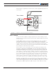
The BK+ terminal is connected internally to the Load+ terminal. The BK- goes to a
MOSFET transistor which will internally connect to the Load- terminal when the resistor is
enabled.
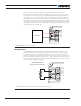
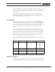
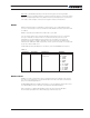
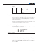
The figures below show the current flow under the various load and regeneration
conditions
FIGURE 11. Current Flow from Pack to Load
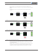
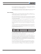
FIGURE 12. Regenerating Energy from Motor
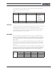
FIGURE 13. Excess Energy Out to Brake Resistor
By default, the Brake output is deactivated and may be controlled by user command or
script. The BMS supports Microbasic scripting that can be written using the PC Utility
accompanying the product.
If a Brake resistor is not needed, two other predefined implementations may be chosen:
a cooling fan or a heater function. These features utilize the temperature thresholds
configured in the utility. This guarantees that the pack is kept warm or cool enough