
Data Sheet

BMS10x0
12 www.roboteq.com Version 1.0 March 2, 2018
conditions under which the charging was paused, different rest times will be set.
Balancing will still be applied as long as the BMS recognizes a charger to be connected.
For example, if one of the cells hits the overvoltage threshold while still charging with a
fast speed (current close to maximum nominal current during charging), the system will
let the battery rest for a longer time than if it were charging with a slow speed, allowing
balancing to operate for more time before charging again. When charging at slow speeds
the battery is not stressed even when operating near the maximum thresholds. However,
if it charges with a high current, an unbalanced cell’s voltage may rise above the threshold
very quickly because of the stresses.
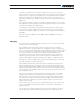
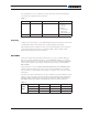
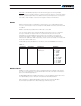
Charger
FIGURE 9. BMS Charge Configuration
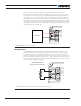
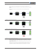
Brake Resistor
The BMS10x0 is equipped with a pair of terminals designed to be connected to an ex-
ternal resistor. Placing an external resistor is optional but recommended when driving a
regenerative load such as a motor. The Brake Resistor is used to release the excess re-
generative energy from the load into the environment as heat in case the current is out of
the safe operating boundaries, the battery is full, or in any other unsafe conditions. The re-
sistor is automatically paralleled with the load when BMS’s algorithm recognizes harmful
excess energy is returning into the pack.
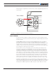
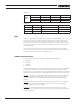
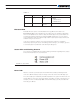
Optional Brake Resistor
or other high current accessory
FIGURE 10. Connection to Brake Resistor or High Power Accessory