
Data Sheet

BMS10x0
www.roboteq.com 11
Counting is considered the dominant indicator. When at least one of the cells reaches
near the minimum or maximum cut off thresholds, where the voltage change is significant
depending on the energy stored in the battery, this cell’s voltage becomes the dominant
indicator for the battery’s SoC. Observing the SoC allows the user to know when the
pack will be isolated from the load (0% SoC) and when it will be isolated from the charger
(100% SoC).
A time variable calculates in real time an estimation of battery’s depletion time in minutes
during discharging. During charging, the time variable provides the time in minutes that is
still needed for the battery to be fully charged.
In summary, the State of Charge is determined as a percentage of the current stored
energy versus the maximum battery capacity while operating in the nominal operating
area which is around 10% to 90% SoC, or based on the cell voltages when below 10% or
above 90%.
The State of Charge is readable via USB, CANbus, RS485, PWMOut and an optional
Bluetooth module.
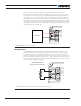
Charging
The easiest and safest charging method for lithium cells is the so-called CC-CV, meaning
Constant Current – Constant Voltage.
Any configurable power supply may be used as a charger, as long as it can deliver
adequate current at the necessary voltage. For configuring the charger’s voltage, please
refer to Cell Chemistry and Voltages section (Page 7, Table 3) and set the charger according
to the max voltage for the corresponding cell number and chemistry. The current should
be set lower or equal to the maximum current during charge specified by the cell
manufacturer. In case this value cannot be obtained, usually it is safe to consider the
maximum current during charge as the nominal cell capacity in Ah divided by 1 h. For
example, a 10 Ah battery would safely operate at up to 10 Ah/ 1 h = 10 A during charge.
Remember to configure your BMS system using the specified thresholds to ensure that
your battery operates in the safe operating area.
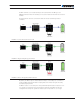
When the BMS system and the charger are properly configured, the charging process
will automatically begin after connecting the respective terminals. At the beginning, the
charger’s voltage will drop delivering 100% of the max charge current. While the pack is
being charged its voltage will at some point reach the nominal fully charged value and the
current will start to drop. The BMS system will continuously monitor and protect the pack
from any dangerous event.
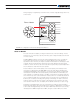
If any of the cell voltages exceeds the maximum threshold or the pack is over heated,
the BMS system will pause the charging process allowing balancing to even out the
differences between the cells. When the system recognizes that the charging speed is
low, meaning slow voltage changes during charging, the BMS will activate the passive
balancing algorithm, extracting energy from the higher voltage cells so that the lower
voltage cells can catch up.
If for any reason the current exceeds the configured thresholds or in case a short circuit
event occurs, the BMS will automatically enable the circuit breaker to deactivate the
dangerous channel.
In a case where the charger parameters are not set with caution and the cells’ voltage
safe operating area is violated, the BMS will pause the process. Depending on the