
Data Sheet


RGDC18xx Motor Controller Datasheet 7
Battery Backed Clock and RAM
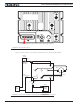
After the controller is powered on, the Power LED will tun on, indicating that the controller is On. The Sta-
tus LED will be flashing at a two second interval. The flashing pattern provides operating or exception sta-
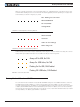
tus information, as shown in Figures 7, 8, and 9:
RS232/USB Mode
Idle - Waiting for Command
RC Pulse Mode
Analog Mode
Under or Over Voltage
Power Stage Off
Short Detected
Overheat
FIGURE 7. Normal Operation Flashing Patterns
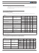
RS232/USB Mode
Idle - Waiting for Command
RC Pulse Mode
Analog Mode
Under or Over Voltage
Power Stage Off
Short Detected
Overheat
FIGURE 8. Exception or Fault Flashing Patterns
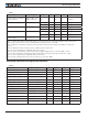
Additional status information may be obtained by monitoring the controller with the PC utility. The commu-
nication LED gives status information on the CAN and USB, as shown in Figure 9:
Always off: No USB, No CAN
Always On: USB Active, No CAN
Flashing On: No USB, CAN Enabled
Flashing Off: USB Active, CAN Enabled
FIGURE 9. Communication LED
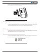
Battery Backed Clock and RAM
The controller includes a real-time clock/calendar and RAM storage for user variables. Both the clock and
the RAM storage require a battery to continue running and for the stored data not to be lost while the
controller is powered down. The battery is not installed by Roboteq. Users who wish to use the clock and/
or battery backed RAM variables must install a battery themselves. The battery socket can be reached by
removing the 6 screws that are holding the cover. Lift the cover to reach the board and insert a 3V, 12.5mm
coin-style battery. Use battery type CR1225 or equivalent.