
Data Sheet


4 RGDC18xx Motor Controller Datasheet Version 1.5 January 17, 2018
Important Warning
Carefully follow the wiring instructions provided in the Power Connection section of the User Manual. The
information on this datasheet is only a summary.
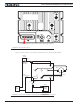
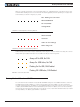
Mandatory Connections
It is imperative that the controller is connected as shown Figure 2, above, in order to ensure a safe and trou-
ble-free operation. All connections shown as thick black lines line are mandatory. The controller must be pow-
ered On/Off using switch SW1on the Power Control input.
Emergency Switch or Contactor
The battery must be connected in permanence to the controller’s B+ terminal via a high-power emergency
switch or contactor as additional safety measure. The user must be able to deactivate the switch or contactor at
any time, independently of the controller state.
Precautions and Optional Connections
Note 1: The power control (pin 25 on DSUb connector) must be grounded to turn off the controller. Floating the
power control or connecting it to a battery will turn on the internal logic.
Note 2: A separate power supply may be used to power the controller’s internal logic to keep the controller alive
in case of voltage drop at the main battery because of motor load. Voltage on Power Control pin must not
exceed 50V Max. Make sure you correctly identified pin 25 before applying voltage to it.
Note 3: Use precharge 1K, 0.5W Resistor to prevent switch arcing.
Note 4: Beware not to create a path from the ground pins on the I/O connector and the battery minus
terminal.
Controller Mounting
During motor operation, the controller will generate heat that must be dissipated. The published amps rating
can only be fully achieved if adequate cooling is provided. Good conduction cooling can be achieved by mount-
ing the controller to a metallic surface, such as the chassis, cabinet, etc.
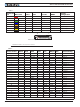
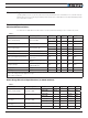
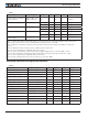
Sensor and Commands Connection
Connection to RC Radio, Microcomputer, Potentiometer, encoders and other low current sensors and actua-
tors is done via the 25-pin DSub connectors and the 8-bit circular connector located at the top of the controller.
The functions of many pins vary depending on controller configuration. Use mating connector Conxall/Switch-
craft model 6282-8SG-3DC, or equivalent. The pin assignments are found in the Tables 1 and 2, below.
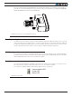
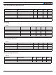
1
2
3
4
5
6
7
8
Top view
Use mating connector
Conxall/Switchcraft
6282-8SG-3DC
FIGURE 3. Circular Connector Pin Locations