
Data Sheet
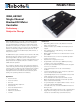


RGDC18xx Motor Controller Datasheet 3
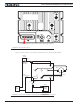
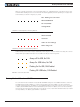
Power Terminals Identifications and Connection
Warning: Properly identify PowerControl pin 25 before applying high voltage to it
FIGURE 1. Top Controller Layout
Figure 2, below, shows how to wire the controller and how to turn power On and Off.
+-
B+
B-
UW
Resistor
1K, 0.5W
Main On/Off
Switch
1A
Note 1
Note 3
Note 2
Note 4
Do not Connect!
Emergency
Disconnect
GND
OFFON
Power
Control
Motor
Sensors
Encoder
+-
Main
Battery
Optional
Backup
Battery
FIGURE 2. Powering the Controller. Thick lines identify MANDATORY connections