
Data Sheet

8 RGDC18xx Motor Controller Datasheet Version 1.5 January 17, 2018
Measured Amps
Including Amps sensors on the wires allows for a fast and efficient feed of information. The controller has sep-
arate built in sensor for measuring the battery amps and the motor amps. Both motor amps and battery amps
are measured in real time.
Electrical Specifications
Absolute Maximum Values
The values in the table below should never be exceeded, Permanent damage to the controller may result.
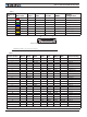
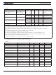
TABLE 3.
Parameter Measure point Model Min Typical Max Units
Battery Leads Voltage Ground to VBat
RGDC1860 63 Volts
RGDC1896 10 0 Volts
Reverse Voltage on Battery Leads Ground to VBat All -1 Volts
Motor Leads Voltage Ground to M+, M-
RGDC1860 63 Volts
RGDC1896 10 0 Volts
Digital Output Voltage Ground to Output pins All 40 Volts
Power Control Ground to PowerControl pin All -1 50 Volts
Analog and Digital Inputs Voltage
Ground to any signal pin on I/O
connectors
All 25 Volts
RS232 pin Voltage
External voltage applied to
Rx pins
All -25 25 Volts
CAN pins Voltage
External voltage applied to
CANH/CANL pins
All -25 25 Volts
Temperature Board All -40 85 ºC
Humidity Board All 100 (3) %
Note 1: Maximum regeneration voltage in normal operation. Never inject a DC voltage from a battery or other fixed source
Note 2: No voltage must be applied on Tx pin
Note 3: Non condensing
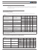
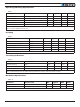
Power Stage Electrical Specifications (at 25oC ambient)
TABLE 4.
Parameter Measure point Model Min Typical Max Units
Battery Leads Voltage Ground to VBat
RGDC
1860 10 (1) 63 Volts
RGDC
1896 40 (1) 10 0 Volts
Motor Leads Voltage Ground to M+, M-
RGDC
1860 63 (2) Volts
RGDC
1896 100 (2) Volts
Over Voltage protec-
tion range
Ground to VBat
RGDC
1860 60 65 (2) Volts
RGDC
1896 96 100 (2) Volts
Under Voltage protec-
tion range
Ground to VBat All 20 20 (4) Volts
Idle Current Consumption VBat or Pwr Ctrl wires All 50 (5) 10 0 mA