
Data Sheet

RGBL18xx Motor Controller Datasheet 9
Status LEDs and Flashing Patterns
USB communication
Only use USB for configuration, monitoring and troubleshooting. USB is not a reliable communication method
when used in electrically noisy environments. If disrupted, communication will not always recover after it is
lost without unplugging and replugging the connector, or restarting the controller. RS232 is the preferred com-
munication method when interfacing to a computer. It is possible for USB and CAN to operate at the same
time on the RGBL18XX. Connecting via USB to a computer will not disable the CAN interface.
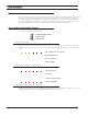
Status LEDs and Flashing Patterns
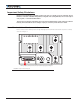
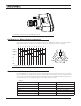
The controller is equipped with three LEDs.
Communication LED
Power LED
Status LED
FIGURE 8. Status LEDs
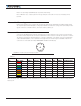
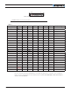
After the controller is powered on, the Power LED will tun on, indicating that the controller is On. The Status
LED will be flashing at a two second interval. The flashing pattern provides operating or exception status infor-
mation.
RS232/USB Mode
Idle - Waiting for Command
RC Pulse Mode
Analog Mode
Under or Over Voltage
Power Stage Off
Short Detected
Overheat
FIGURE 9. Normal Operation Flashing Patterns
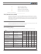
RS232/USB Mode
Idle - Waiting for Command
RC Pulse Mode
Analog Mode
Under or Over Voltage
Power Stage Off
Short Detected
Overheat
FIGURE 10. Exception or Fault Flashing Patterns
Additional status information may be obtained by monitoring the controller with the PC utility. The communica-
tion LED gives status information on the CAN and USB, as shown in Figure 11: