
Data Sheet

8 RGBL18xx Motor Controller Datasheet Version 1.2 April 19, 2018
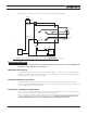
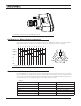
Connecting Resolver
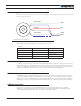
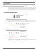
Resolver wiring is similar to a Sin/Cos sensor with the addition of an excitation signal. Figure 7, below, shows
the necessary connections.
FIGURE 7. Resolvering Wiring
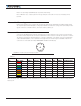
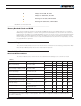
Table 5 shows the signals assignment on the 8-pin circular connector.
TABLE 5.
Signal Pin Number Description
ASIN 4 Sin input
ACOS 5 Cos input
EXC 7 Excitation output
GND 8 Ground
Enabling Analog Commands
For safety reasons, the Analog command mode is disabled by default. To enable the Analog mode, use the PC
utility and set Analog in Command Priority 2 or 3 (leave Serial as priority 1). Note that by default the additional
securities are enabled and will prevent the motor from starting unless the potentiometer is centered, or if the
voltage is below 0.25V or above 4.75V. Use the PC utility to enable and assign analog inputs.
RS485 Communication
The RGBL18xxx has a half-duplex RS485 interface. Two signals are present on the 25-pin DSub connector for
connecting to RS485 networks. Connecting these two wires with the correct polarity is all that is needed to
establish a connection. The RS485+ is the positive signal and RS485- is the inverted signal. Once enabled, the
RS485 can be used to communicate data under the Modbus protocol, or Roboteq’s native serial commands.
CAN Bus Operation
The controller can interface to a standard CAN Bus network, using four possible protocols: Standard
CANOpen, a simple and efficient meshed networking scheme (RoboCAN), and two simplified proprietary
schemes (MiniCAN and RawCAN). Please refer to the User Manual for details.
Primary
Secondary 1
ASIN
ACOS
EXC
GND
Secondary 2