
Data Sheet

RGBL18xx Motor Controller Datasheet 7
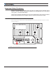
Connection to SSI Absolute Encoder
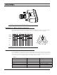
FIGURE 5 . DSub Connector with Waterproof Hood
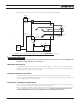
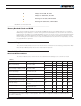
Hall Sensor vs. Motor Output sequencing
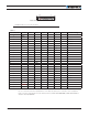
The controller requires the Hall sensors inside the motor to be 120 degrees apart. The controller’s 3-phase
bridge will activate each of the motor winding according to the sequence, as shown in Figure 6:
U
VW
1234561
4
2
5
3
6
4
1
5
2
6
3
Hall
A
Hall
B
Hall
C
U
V
W
+
--
-- --
-- --
--
++ ++
++ ++
++ +
FIGURE 6. Hall Sensors Sequence
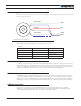
Connection to SSI Absolute Encoder
In Sinusoidal Mode, the controller can use motors equipped with absolute angle sensors with SSI interface.
When enabled, the SSI signals are found on the 8-pin circular connector that is otherwise used for the Hall
Sensors. The controller issues a differential clock signal and expects a 12-bit differential data signal from the
encoder. Table 4 shows the signals assignment on the 8-pin circular connector.
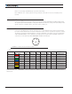
TABLE 4.
Signal Pin Number Description
5V 1 5V Power Out
CLK+ 2 Differential Clock Output +
CLK- 3 Differential Clock Output -
DATA+ 4 Differential Clock Output +
DATA- 5 Differential Clock Output -
GND 8 Ground