
Data Sheet

RGBL18xx Motor Controller Datasheet 5
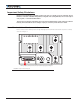
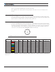
Sensor and Commands Connection
Note 3: Use precharge 1K, 0.5W Resistor to prevent switch arcing.
Note 4: Beware not to create a path from the ground pins on the I/O connector to the battery minus
terminal.
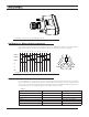
Controller Mounting
During motor operation, the controller will generate heat that must be dissipated. The published amps rating
can only be fully achieved if adequate cooling is provided. Good conduction cooling can be achieved by mount-
ing the controller to a metallic surface, such as the chassis, cabinet, etc.
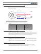
Sensor and Commands Connection
Connection to RC Radio, Microcomputer, Potentiometer, encoders and other low current sensors and actua-
tors is done via the 25-pin DSub connectors and the 8-bit circular connector located at the top of the controller.
The functions of many pins vary depending on controller configuration. Use mating connector Conxall/Switch-
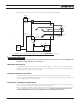
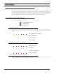
craft model 6282-8SG-3DC, or the equivalent. Pin assignments are found in Figure 3 and Table 2 below. The
color are those of the cable assembly CABLE-RGBx1 available from Roboteq.
1
2
3
4
5
6
7
8
Top view
Use mating connector
Conxall/Switchcraft
6282-8SG-3DC
FIGURE 3. Circular Connector male pins location
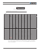
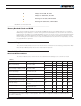
TABLE 2.
Connector
Pin Wire Color Power
Hall
Sensors Ana Encoder SSI DOUT
Default
Configuration
1 Red +5V
2 White Hall A ENC3 CLK+ Hall Input
3 Green Hall B ENC3 CLK- Hall Input
4 Blue Hall C ASIN DATA+ Hall Input
5 Orange ACOS DATA- Unused
6
Brown
DOUT 5 Digital Output
7 Yellow EXC
8 Black GND
NOTE: The above cable, CABLE-RGBx1, can be ordered from the Ordering Online section of Roboteq’s website at https://www.
roboteq.com.