
Data Sheet

4 RGBL18xx Motor Controller Datasheet Version 1.2 April 19, 2018
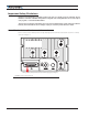
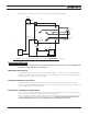
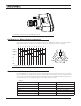
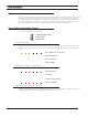
Figure 2, below, shows how to wire the controller and how to turn power On and Off.
+-
B+
B-
U
U
V
V
W
W
Resistor
1K, 0.5W
Main On/Off
Switch
1A
Note 1
Note 3
Note 2
Note 4
Do not Connect!
Emergency
Disconnect
GND
OFF ON
Power
Control
Motor
Sensor
s
Hall A/B/C
or Encoder
+-
Main
Battery
Optional
Backup
Battery
FIGURE 2. Powering the Controller. NOTE: Thick lines identify MANDATORY connections
Important Warning
Carefully follow the wiring instructions provided in the Power Connection section of the User Manual. The
information on this datasheet is only a summary.
Mandatory Connections
It is imperative that the controller is connected, as shown in Figure 2, in order to ensure a safe and trouble-free
operation. All connections shown as thick black lines line are mandatory. The controller must be powered On/
Off using switch SW1on the Power Control input.
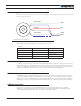
Emergency Switch or Contactor
The battery must be connected in permanence to the controller’s B+ terminal via a high-power emergency
switch or contactor as additional safety measure. The user must be able to deactivate the switch or contactor at
any time, independently of the controller state.
Precautions and Optional Connections
Note 1: The power control (pin 25 on DSUb connector) must be grounded to turn off the controller. Floating the
power control or connecting it to a battery will turn on the internal logic.
Note 2: A separate power supply may be used to power the controller’s internal logic to keep the controller alive
in case of voltage drop at the main battery because of motor load. Voltage on Power Control pin must not
exceed 50V Max. Make sure you correctly identified pin 25 before applying voltage to it.