
Data Sheet

RGBL18xx Motor Controller Datasheet 11
Electrical Specifications
Power Stage Electrical Specifications (at 25ºC ambient)
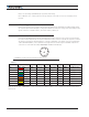
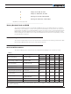
TABLE 7.
Parameter Measure point Model Min Typical Max Units
Battery Leads Voltage Ground to VBat
RGBL1860 10 (1) 63 Volts
RGBL1896 40 (1) 10 0 Volts
Motor Leads Voltage Ground to M+, M-
RGBL1860 63 (2) Volts
RGBL1896 100 (2) Volts
Over Voltage protection
range
Ground to VBat
RGBL1860 65 (2) Volts
RGBL1896 96 100 (2) Volts
Under Voltage protection
range
Ground to VBat All 20 20 (4) Volts
Idle Current Consumption VBat or Pwr Ctrl wires All 50 (5) 10 0 mA
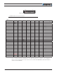
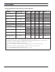
ON Resistance (Excluding
wire resistance)
VBat to A/B/C , plus
A/B/C to Ground
All 0.7 mOhm
Max Current for 30s Motor current
RGBL1860 400 Amps
RGBL1896 300 Amps
Continuous Max Current Motor current
RGBL1860 300 (6) Amps
RGBL1896 200 (6) Amps
Current Limit range Motor current
RGBL1860 10 300 (7) 400 Amps
RGBL1896 10 200 (7) 300 Amps
Motor Acceleration/Dece-
leration range
Motor current All 10 0 500 (8) 65000 milliseconds
Note 1: Voltage may drop to 0 if backup supply is connected to Power Control pin. Negative voltage will cause a
large surge current. A Protection is fuse needed if battery polarity inversion is possible
Note 2: Maximum regeneration voltage in normal operation. Never inject a DC voltage from a battery or other fixed source
Note 3: Minimum voltage must be present on VBat or Power Control wire
Note 4: Factory default value. Adjustable in 0.1V increments
Note 5: Current consumption is lower when higher voltage is applied to the controller’s VBat or PwrCtrl
wires
Note 6: Estimate. Limited by heatsink temperature. Current may be higher with better cooling
Note 7: Factory default value. Adjustable in 0.1A increments
Note 8: Factory default value. Time in ms for power to go from 0 to 100%