
Data Sheet

MDC22xx Motor Controller Datasheet 9
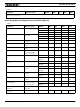
Electrical Specifications
Power Stage Electrical Specifications (at 25oC ambient)
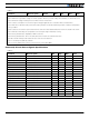
Note 1: Maximum regeneration voltage in normal operation. Never inject a DC voltage from a battery or other fixed source
Note 2: Non-condensing
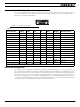
TABLE 7.
Parameter Measure point Models Min Typ Max Units
Battery Leads Voltage Ground to VMot MDC2230 0 (1) 30 Volts
MDC2250 0 (1) 50 Volts
MDC2460 0 (1) 62 Volts
Motor Leads Voltage Ground to M1+, M1-,
M2+, M2-
MDC2230 0 (1) 30 (2) Volts
MDC2250 50 (2) Volts
MDC2460 62 (2) Volts
Power Control Voltage Ground to Power Con-
trol wire
All 0 (1) 50 Volts
Minimum Operating Voltage VMot or Pwr Ctrl
wires
All 9 (3) Volts
Idle Current Consumption VMot or Pwr Ctrl
wires
All 50 100 (4) 150 mA
ON Resistance VMot to M+, plus M-
to Ground at 100%
power. Per channel
All 6 mOhm
Max Current per channel for
30s
Motor current MDC2230/50/60 60 (5) Amps
MDC2230S/
50S/60S
120 (5)(6) Amps
Continuous Max Current per
channel
Motor current MDC2230/50/60 50 (6)(7) Amps
MDC2230S/
50S/60S
100 (6)(7) Amps
Current Limit range Ch1 or Ch2 Motor
current
MDC2230/50/60 10 50 (8) 60 Amps
MDC2230S/
50S/60S
10 100 (8) 120 (6) Amps
Stall Detection Amps range Ch1 or Ch2 Motor
current
MDC2230/50/60 10 60 (8) 60 Amps
MDC2230S/
50S/60S
10 120 (8) 120 (6) Amps
Stall Detection timeout range Ch1 or Ch2 Motor
current
All 1 65000 (9) 65000 millisec-
onds
Short Circuit Detection
threshold (10)
Between Motor wires
or Between Motor
wire and Ground
MDC2230/50/60 140 (11) 400 (11) Amps
MDC2230S/
50S/60S
280 800 Amps
Short Circuit Detection
threshold
Between Motor wires
and VMot
All No Protection. Permanent damage will result
Motor Acceleration/Decelera-
tion range
Ch1 or Ch2 All 100 500 (12) 65000 millisec-
onds
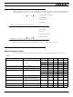
TABLE 6.
Parameter Measure point Model Min Typ Max Units