
Data Sheet

8 MDC22xx Motor Controller Datasheet Version 1.2. January 18, 2014
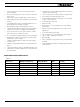
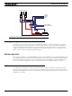
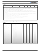
Status LED Flashing Patterns
After the controller is powered on, the Power LED will turn on, indicating that the controller is On. The Status LED
will be flashing at a 2 seconds interval. The flashing pattern provides operating or exception status information.
Additional status information may be obtained by monitoring the controller with the PC utility.
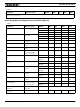
Electrical Specifications
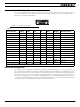
Absolute Maximum Values
The values in the table below should never be exceeded, permanent damage to the controller may result.
TABLE 6.
Parameter Measure point Model Min Typ Max Units
Battery Leads Voltage Ground to VMot MDC2230 35 Volts
MDC2250 50 Volts
MDC2460 62 Volts
Reverse Voltage on Battery Leads Ground to VMot All -1 Volts
Power Control Voltage Ground to Pwr Control wire All 50 Volts
Motor Leads Voltage Ground to M1+, M1-, M2+, M2- MDC2230 30 Volts
MDC2250 50 (1) Volts
MDC2460 62 (1) Volts
Digital Output Voltage Ground to Output pins All 30 Volts
Analog and Digital Inputs Voltage Ground to any signal pin on
15-pin and encoder connectors
All 15 Volts
RS232 I/O pins Voltage External voltage applied to Rx/
Tx pins
All 15 Volts
Temperature Board All -40 85 oC
Humidity Board All 100 (2) %
RS232/USB Mode
Idle - Waiting for Command
RC Pulse Mode
Analog Mode
FIGURE 14. Normal Operation Flashing Patterns
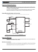
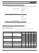
Under or Over Voltage
Power Stage Off
Short Detected
Overheat
FIGURE 15. Exception or Fault Flashing Patterns