
Data Sheet

6 MDC22xx Motor Controller Datasheet Version 1.2. January 18, 2014
Commands and I/O Connections
Connection to RC Radio, Microcomputer, Joystick and other low current sensors and actuators is done via the 15
connector located in front of the board. The functions of many pins vary depending on user configuration. Pin
assignment is found in the table below.
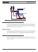
Default I/O Configuration
The controller can be configured so that practically any Digital, Analog and RC pin can be used for any purpose.
The controller’s factory default configuration provides an assignment that is suitable for most applications. The
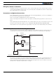
figure below shows how to wire the controller to two analog potentiometers, an RC radio, and the RS232 port. It
also shows how to connect the two outputs to motor brake solenoids. You may omit any connection that is not
required in your application. The controller automatically arbitrates the command priorities depending on the pres-
ence of a valid command signal in the following order: 1-RS232, 2-RC Pulse, 3-None. If needed, use the Roborun+
PC Utility to change the pin assignments and the command priority order.
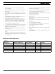
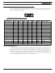
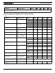
TABLE 5.
Connector Pin Power Dout Com RC Ana Dinput Default Config
1 DOUT1 Motor Brake
9 DOUT2 Safety Contactor
2 TxOut RS232Tx
10 RC5 ANA1 DIN5 AnaCmd1 (1)
3RxInRS232Rx
11 RC4 ANA4 DIN4 AnaCmd2 (1)
4 RC1 DIN1 RCRadio1
12 RC3 ANA3 DIN3 Unused
5 GND
13 GND
6 CANL CAN Low
14 5VOut
7 CANH CAN High
15 DIN6 Unused
8 RC2 ANA2 DIN2 RCRadio2
Note 1: Analog command is disabled in factory default configuration.
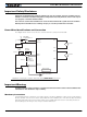
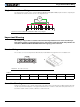
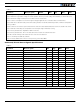
18
915
FIGURE 12. Connector pin locations