
Data Sheet

4 MDC22xx Motor Controller Datasheet Version 1.2. January 18, 2014
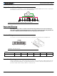
Emergency Switch or Contactor
The battery must be connected in permanence to the controller’s VMot power via an input emergency switch or
contactor SW2 as additional safety measure. The user must be able to deactivate the switch or contactor at any
time, independently of the controller state.
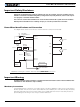
Precautions and Optional Connections
Note 1: Backup battery to ensure motor operation with weak or discharged batteries, connect a second battery to
the Power Control wire/terminal via the SW1 switch.
Note 2: Use precharge 1K, 0.5W Resistor to prevent switch arcing.
Note 3: Insert a high-current diode to ensure a return path to the battery during regeneration in case the fuse is
blown.
Note 4: Optionally ground the VMot tabs when the controller is Off if there is any concern that the motors could
be made to spin and generate voltage in excess of 30V (MDC2230), 50V (MDC2250) or 60V (MDC2460).
Note 5: Beware not to create a path from the ground pins on the I/O connector and the battery minus terminal.
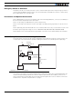
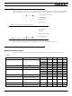
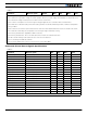
Use of Safety Contactor for Critical Applications
An external safety contactor must be used in any application where damage to property or injury to person can
occur because of uncontrolled motor operation resulting from failure in the controller’s power output stage.
The contactor coil must be connected to a digital output configured to activate when “No MOSFET Failure”. The
controller will automatically deactivate the coil if the output is expected to be off and battery current of 1A or
more is measured for more than 0.5s. This circuit will not protect against other sources of failure such as those
described in the “Important Safety Disclaimer” on page 3.
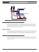
PwrCtrl
SW1 Main
On/Off Switch 1A
F2
1A
Diode
>20A
Resistor
1K, 0.5W
+-
F1
I/O Connector
VMot
to +40V Max
Digital Out
Ground
Ground
Main
Battery
FIGURE 9. Contactor wiring diagram