
Data Sheet

MDC22xx Motor Controller Datasheet 3
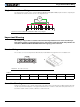
Power Wires Identifications and Connection
Important Safety Disclaimer
Dangerous uncontrolled motor runaway condition can occur for a number of reasons, including, but not
limited to: command or feedback wiring failure, configuration error, faulty firmware, errors in user script or
user program, or controller hardware failure.
The user must assume that such failures can occur and must make his/her system safe in all conditions.
Roboteq will not be liable in case of damage or injury as a result of product misuse or failure.
Power Wires Identifications and Connection
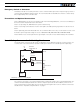
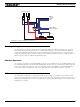
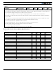
The diagram below shows how to wire the controller and how to turn power On and Off.
Important Warning
Carefully follow the wiring instructions provided in the Power Connection section of the User Manual. The
information on this datasheet is only a summary.
Mandatory Connections
It is imperative that the controller is connected as shown in the above diagram in order to ensure a safe and trou-
ble-free operation. All connections shown as thick black lines are mandatory. The controller must be powered On/
Off using switch SW1on the Power Control Header. Use a suitable high-current fuse F1 as a safety measure to
prevent damage to the wiring in case of major controller malfunction.
Motor 1
VMot
PwrCtrl
SW1 Main
On/Off Switch 1A
F2
1A
Diode
>20A
Resistor
1K, 0.5W
+-
SW2
Emergency
Contactor or
Cut-off Switch
F1
M1+
M1-
M2+
M2-
I/O Connector
VMot
Ground
Ground
Ground
Motor 2
Main
Battery
Backup
Battery
Note 5
Do not Connect!
Note 1
Note 4
Note 3 Note 2
FIGURE 8. Powering the controller. Thick lines identify MANDATORY connections