
Data Sheet

10 MDC22xx Motor Controller Datasheet Version 1.2. January 18, 2014
Command, I/O and Sensor Signals Specifications
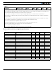
Note 1: Negative voltage will cause a large surge current. Protection fuse needed if battery polarity inversion is possible
Note 2: Maximum regeneration voltage in normal operation. Never inject a DC voltage from a battery or other fixed source
Note 3: Minimum voltage must be present on VMot or Power Control wire
Note 4: Current consumption is lower when higher voltage is applied to the controller’s VMot or PwrCtrl wires
Note 5: Max value is determined by current limit setting. Duration is estimated and is dependent on ambient temperature
cooling condition
Note 6: Current is sum of both synchronized channels. Current must be balanced between channel to obtain max current.
Note 7: Estimate. Limited by case temperature. Current may be higher with better cooling
Note 8: Factory default value. Adjustable in 0.2A increments
Note 9: Factory default value. Time in ms that Stall current must be exceeded for detection
Note 10: Controller will stop until restarted in case of short circuit detection
Note 11: Sensitivity selectable by software
Note 12: Factory default value. Time in ms for power to go from 0 to 100%
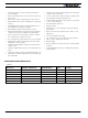
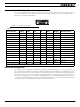
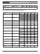
TABLE 8.
Parameter Measure point Min Typ Max Units
Main 5V Output Voltage Ground to 5V pins on 4.6 4.75 4.9 Volts
5V Output Current 5V pins on Hall Connector and DSub15 200 (1) mA
Digital Output Voltage Ground to Output pins 40 Volts
Digital Output Current Output pins, sink current 1 Amps
Output On resistance Output pin to ground 0.75 1.5 Ohm
Output Short circuit threshold Output pin 1.05 1.4 1.75 Amps
Input Impedances AIN/DIN Input to Ground 53 kOhm
Digital Input 0 Level Ground to Input pins -1 1 Volts
Digital Input 1 Level Ground to Input pins 3 15 Volts
Analog Input Range Ground to Input pins 0 5.1 Volts
Analog Input Precision Ground to Input pins 0.5 %
Analog Input Resolution Ground to Input pins 1 mV
Pulse durations Pulse inputs 20000 10 us
Pulse repeat rate Pulse inputs 50 250 Hz
Pulse Capture Resolution Pulse inputs 1 us
Frequency Capture Pulse inputs 100 10000 Hz
Encoder count Internal -2.147 2.15 10^9 Counts
Encoder frequency Encoder input pins 250 kHz
Note 1: Sum of all 5VOut outputs
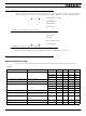
TABLE 7.
Parameter Measure point Models Min Typ Max Units