
Data Sheet

MDC1xxx Motor Controller Datasheet 9
Electrical Specifications
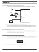
Beware that regenerative braking can create high voltage at the controller's power inputs. Use the con-
troller only with batteries. See user manual for special precautions when using a power supply.
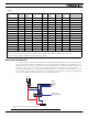
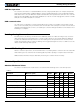
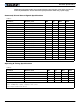
Command, I/O and Sensor Signals Specifications
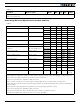
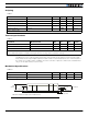
Operating & Timing Specifications
TABLE 5.
Parameter Measure point Min Typ Max Units
Main 5V Output Voltage Ground to 5V pin on DSub15 4.7 4.9 5.1 Volts
5V Output Current 5V pin on DSub15 100 mA
Digital Output Voltage Ground to Output pins 40 Volts
Digital Output Current Output pins, sink current 1 Amps
Output On resistance Output pin to ground 0.75 1.5 Ohm
Output Short circuit threshold Output pin 1.05 1.4 1.75 Amps
Input Impedances AIN/DIN Input to Ground 53 kOhm
Digital Input 0 Level Ground to Input pins -1 1 Volts
Digital Input 1 Level Ground to Input pins 3 15 Volts
Analog Input Range Ground to Input pins 0 5.1 Volts
Analog Input Precision Ground to Input pins 0.5 %
Analog Input Resolution Ground to Input pins 1 mV
Pulse durations Pulse inputs 20000 10 us
Pulse repeat rate Pulse inputs 50 250 Hz
Pulse Capture Resolution Pulse inputs 1 us
Frequency Capture Pulse inputs 100 10000 Hz
Encoder count Internal -2.147 2.147 10^9 Counts
Encoder frequency Encoder input pins 1M(1) Counts/s
Note1: Encoder input requires RC inputs 3, 4, 5 and 6 to be disabled. Encoders are enabled in factory default.
TABLE 6.
Parameter Measure Point Min Typ Max Units
Command Latency Command to output change 0 0.5 1 ms
PWM Frequency Motor outputs 10 18 (1) 20 kHz
Closed Loop update rate Internal 1000 Hz
RS232 baud rate Rx & Tx pins 115200 (2) Bits/s
RS232 Watchdog timeout Rx pin 1 (3) 1000 65000 ms
Note 1: May be adjusted with configuration program
Note 2: 115200, 8-bit, no parity, 1 stop bit, no flow control
Note 3: May be disabled with value 0